DIY Loudspeakers: HOME INDEX UPDATES RESPONSE WHAT'S NEW
B&W 802 s3 Up-Grade
Kit
Copyright 2016-21 © Troels Gravesen
Go to on this page:
CROSSOVER
MEASUREMENTS
Up-Grade KIT
CROSSOVER LAYOUT
SOUND
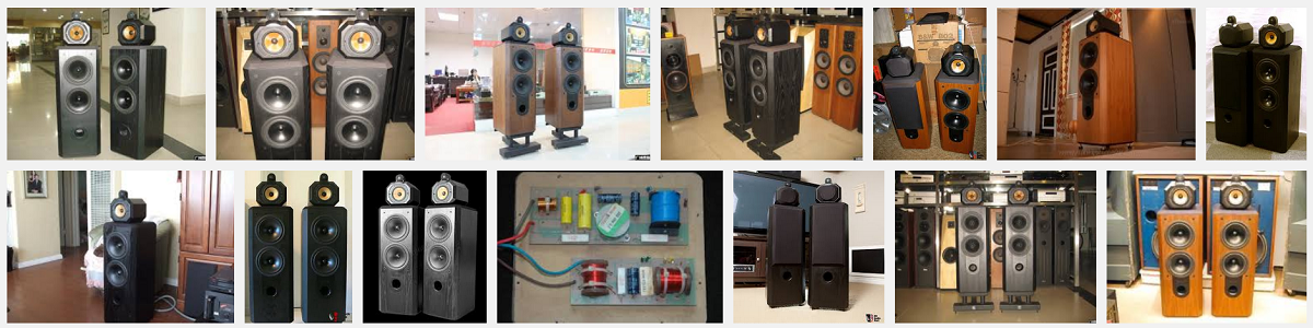
Google search reveals a multitude if finishes
of the B&W 802.
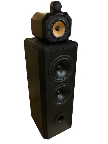
A client brought in these B&W 802 s3 speakers for a possible upgrade of
crossover. Not necessarily a new crossover, but at least a replacement
of existing components with the best possible coils and caps within a
decent price range, hence this article on how to up-grade your nineties
B&W speakers.
Before starting any measurements I set up the speakers in my living room
and replacing my ATS4, I experienced a somewhat smaller speaker with
less visceral impact in the bass area and a somewhat less weighty lower
midrange presentation, giving less fullness to vocals. After all, this
is a smaller speaker and should be judged by that standard. I played
music I knew well and I played some at really loud level and the 801
played it all without apparent distortion or sign of aggressiveness in
any particular frequency band. I seems this speaker plays it all without
being discriminating towards any particular type of music. I found the
treble level well balanced, but some part of the midrange a little
forward making vocals a little shut in like lacking the
upper-mid/lower-treble.
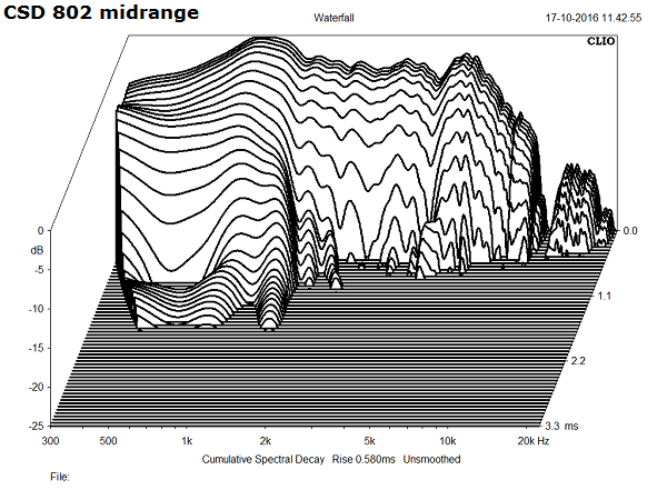
Doing measurements of the 802 proved a surprising adventure,
revealing quite an un-linear response as can be seen below, and I could
understand my listening impressions, because around 1.5 kHz the overall
level drops some 4-5 dB relative to the average midrange level. Hmm...
The 802 midrange driver has quite a good dispersion and after a lot of
tweaking and actually setting up a totally reworked crossover making an
overall flat response, I started thinking the actual voicing appear
deliberate rather than a result of poor engineering, although it looks
so. Has to be said that all of the midrange and treble range from 1.5-20
kHz is fairly flat albeit at different levels. The roll-off of all
drivers look really good with no apparent cone break-up problems at all.
The actual crossover displays a 4th order topology with points of
crossover ~475 and ~3300 Hz. Did I say I was impressed by the treble
performance of this alu dome? Smooth and easy on the ear and not a hint
of old time alu dome harshness.
Download 802 s3 manual here.
Before and after crossovers. Click images to vie large.

The crossover uses is an LR4 crossover topology realised from a third
order filter to bass and tweeter
and from second order filters for the midrange, the latter due to it's
inherent roll-off characteristics.
The coils are non-standard coils with regard to inductance and series
resistance,
but fortunately Jantzen Audio can deliver anything in this area.
I decided not to use air-cored coils for the bass section. 2.0 mH from
1.8 mm wire would still make DCR = 0.33 Ohm and 0.66 Ohm in total in
series with the bass drivers. Too much, hence cored coils, but from
thicker wire than the original crossover.
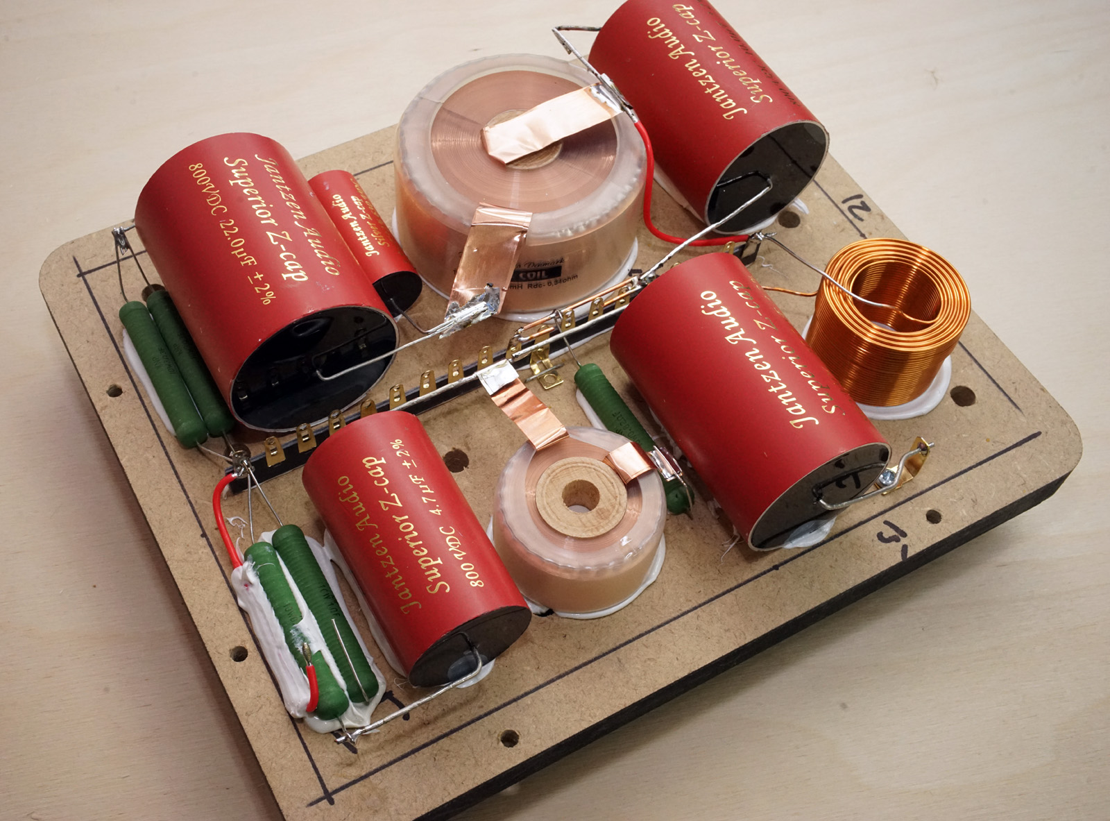
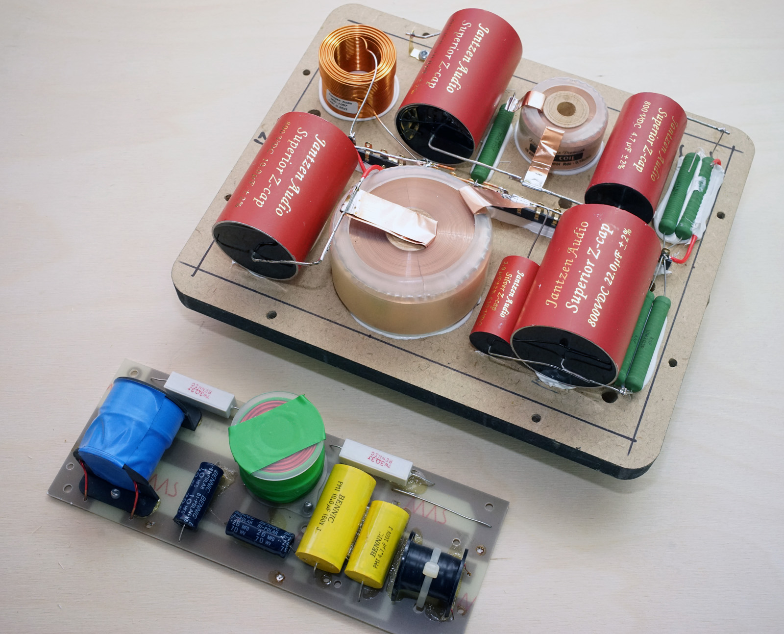
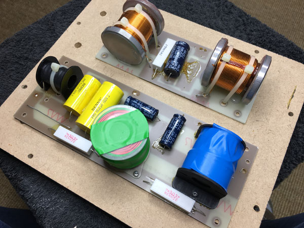
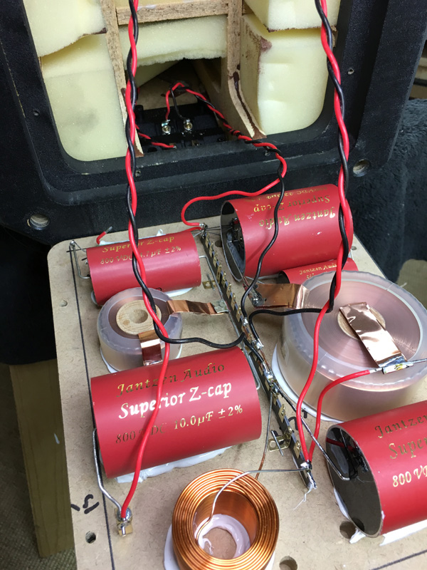
The new crossovers. Click images to view
large
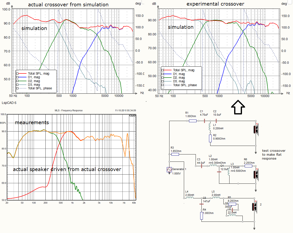
What seen above is the simulations and performances performed from as-is crossover and an experimental crossover, the latter producing a more flat response. The thing is the the "perfect" crossover makes a too forward sounding speaker, too much right in your face. I link this to the overall power response being excessive in upper mid/lower treble from the "flat" crossover due to dispersion of the small midrange driver. Sometimes this goes well, sometimes it doesn't, and the sad thing is that we're unable to predict this alone from the dispersion characteristics of the midrange driver. It must be tried and the overall voicing of a speaker system depends on listening tests of a wide range of musical genres trying to balance power response with a proper tonal balance.
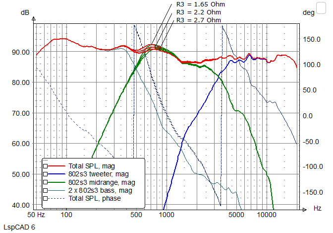
You can obviously experiment with midrange attenuation if you find the
speaker a little too forward.
Here you have what happens from R3 = 1.65 Ohm (default), 2.2 Ohm and 2.7
Ohm.
This nicely flattens the bump at 700 Hz without impacting
upper-mid/lower-treble.
A single 10 watt resistor will do.
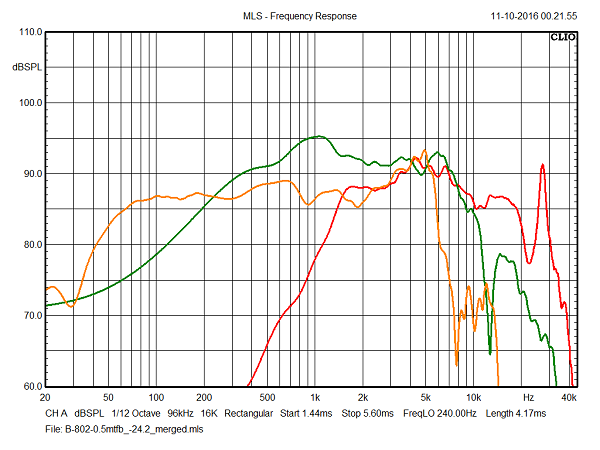
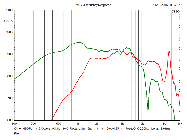
Above to the left: SPL from drivers measured at 0.5 meter distance with an input equal to 2.8V/1meter. Sensitivity of the bass drivers is around 87 dB, where the middriver is highly efficient with around 92 dB/2.8V. Tweeter level a little uneven, but around 87 dB possible due to the 10-20 kHz range. The small midrange cabinet makes a serious bump around 700-1500 Hz, not an easy response when it comes to crossover. Above to the right mid and tweeter with different scaling.
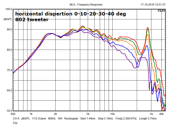
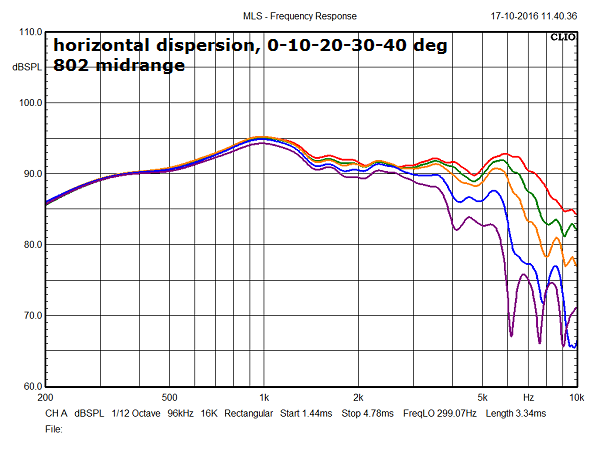
Above and below horizontal dispersion of tweeter and midrange driven directly without crossover. Both units display good dispersion, which may account for the need to suppress lower-treble range to balance the overall presentation. The midrange bump at 1 kHz poses a problem in terms of crossover design and not fully flattened out, puts its make on the overall voicing of this system.
Final results from up-graded crossovers.
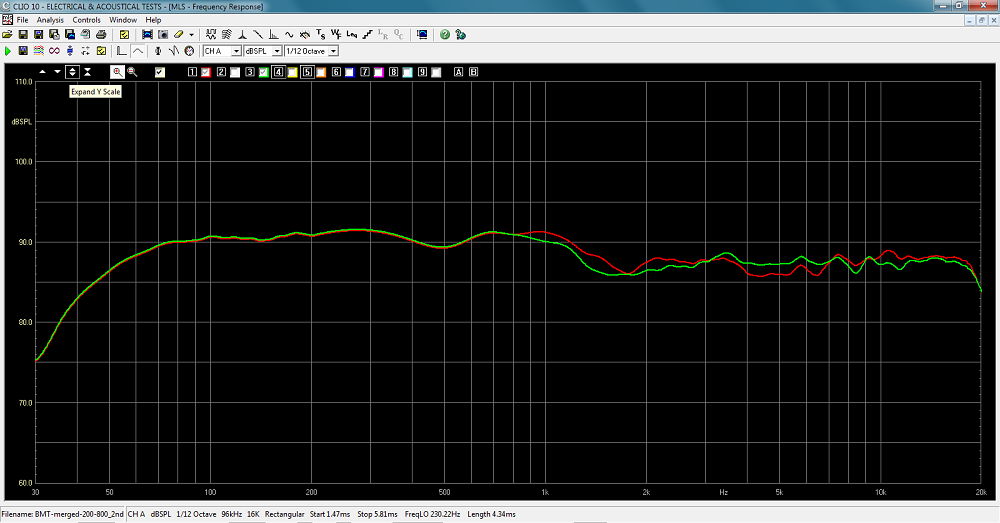
Final results from the two speakers. Response within 1 dB.
Minor differences in performances from the two midrange drivers, but
fully acceptable (one dust cap had been re-glued).
The before noticeable bump at 700-1000 Hz seems less prominent here.
Maybe some of the old electrolytic caps had their time.
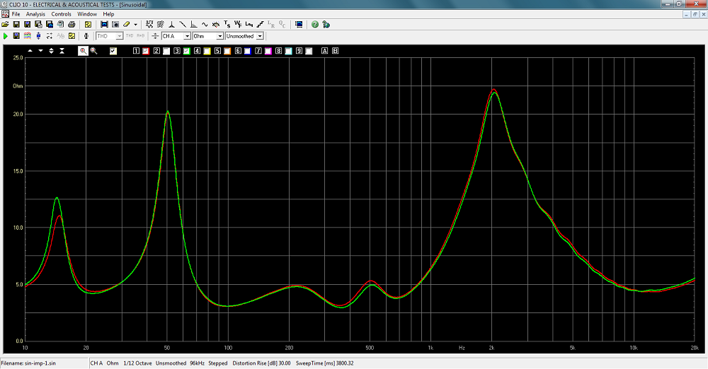
Final system impedance from the two speakers.
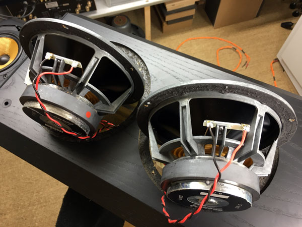
PICS from the workshop
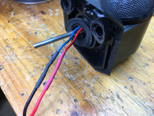
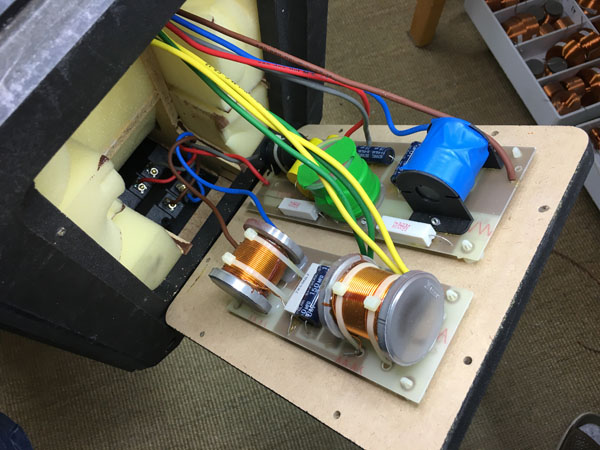
All wires are replaced by 1.3 mm silver plated copper in Teflon sleeves. We can't replace than last 3-4 centimeters to the tweeter, but what's seen above will do. Make sure you get driver polarity right. Tweeter red is PLUS, tweeter blue is MINUS.
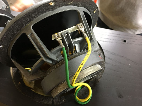
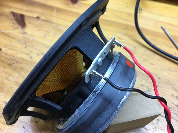
Above left: For the bass drivers the terminal to the right, when seen up-right, is PLUS (original yellow wire). Right: Midrange driver with the PLUS terminal to the right when seen up-right. Replace like seen above and ditch the connectors and solder wires directly to the terminals.
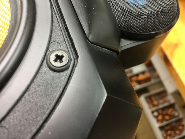
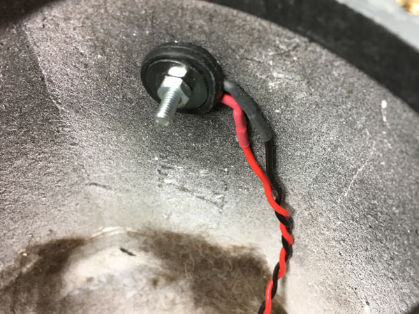
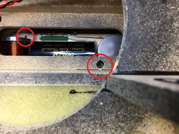
Left: The midrange driver is mounted with metric screws and a rubber grommet
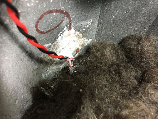
is inserted to reduce vibration. Nice details. Right: When you have pulled new wires through the hole to the bass
cabinet, make sure adding a lot of filler to eliminate any ventilation
to the bass cabinet. I used the same stuff as I use for mounting
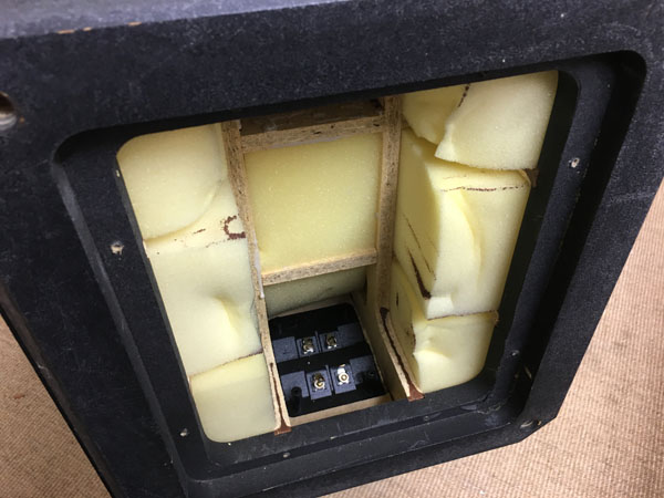
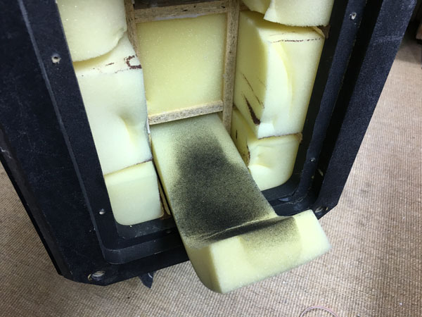
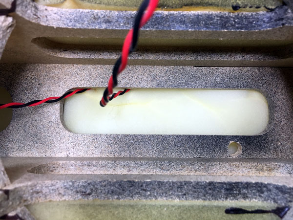
crossover. The mid cabinet is closed and completely
filled with damping material. The midrange cabinet appear to be made
from low-resonance material and is attached to the bass cabinet by a
single threaded rod allowing wires to go through and the cabinet to be
rotated. The latter may not be such a great idea as it allows the mid
cabinet to rock slightly. Ideally insert a robber wedge at the rear
between the two cabinets to reduce rocking once optimal position has
been established.
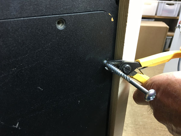
Left: Removing the bottom panel with the crossover may take a little
help from a 6 mm screw and a plier. Gently loosen the base plate. Right:
To enable removing the bottom panel you have to cut the two fasteners
holding the wires in place behind the bass drivers.
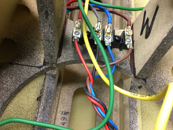
Left: Cut all wires from this terminal block, pull out the crossover and de-solder all wires including those from the binding posts.
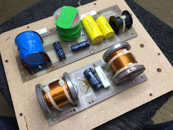
The original crossover with electrolytic cap for the midrange and Bennic for the tweeter. Coils are not necessarily bad, but the midrange coils are not baked (backlack/self-binding wire) as should be to reduce vibration. New coils obviously are either baked or the tightly wound foil coils.
Pull out the rear middle section damping material and insert the bass crossover. Push up to the lower bass driver hole and fasten with two screws.
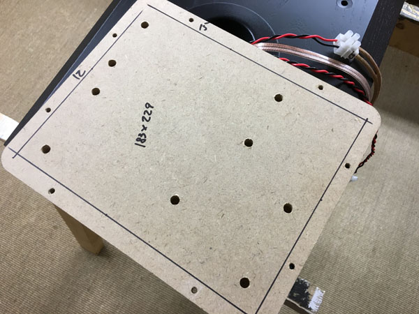
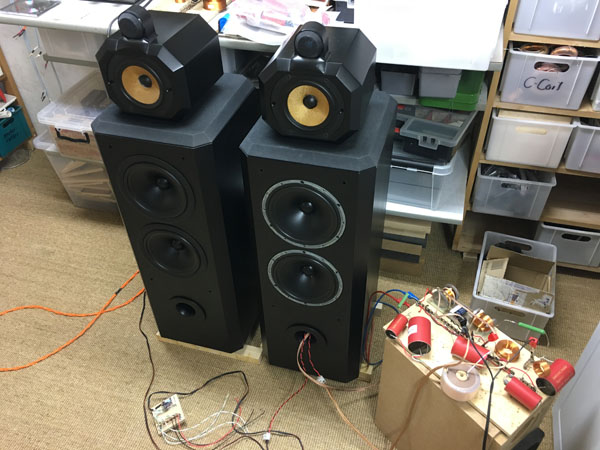
Above to the left the base plate holding the original crossover. The area that can be used for the new crossover is ~183 x 229 mm. To the right first time set-up of new crossover allowing me to AB test the two speakers. Quite a difference in sound I must say.
Above, left: The mid-tweeter section is the easy part. Connect input to
terminals and connect mid and tweeter.
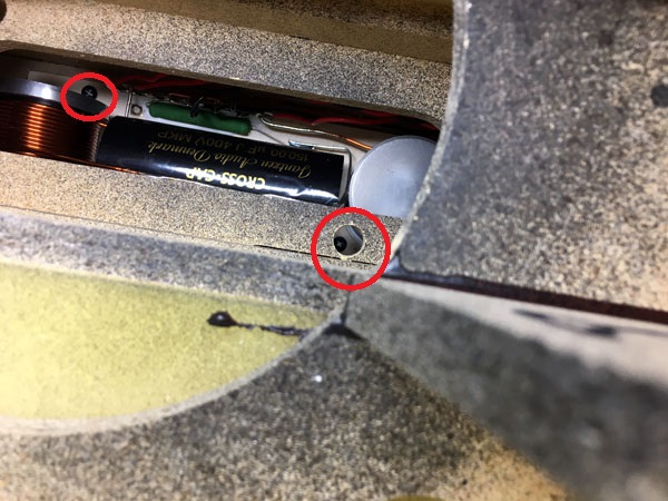
Above, right: Drill a 12 mm hole in the mid bracing through the lower
bass hole to allow fastening one of the two screws holding the bass
crossover to the rear panel. One the picture below to the left you can
see the two screws in place.
Pull the wires to the bass drivers and insert 1/3 of the foam bar on top
of the crossover.
The long foam bar from the center rear section is cut into three pieces
and inserted from front through bass holes and the lower from the
bottom.
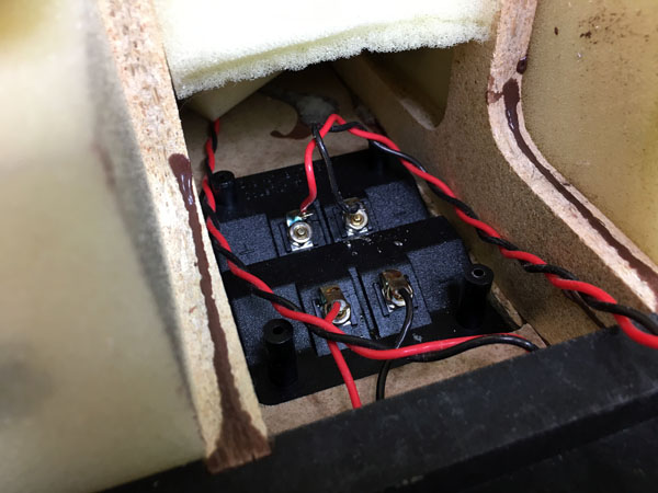
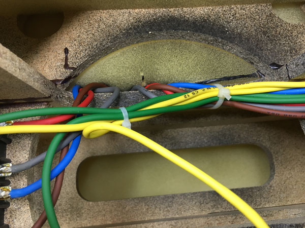
Above to the left the terminals allowing bi-wiring. To the right wires
soldered to the bass drivers.
There are some hidden information in the list below to avoid any dealer to do a copy-paste, and that's the series resistance of the coils. These need to be fairly accurate for some of the coils. For the bass coils I have chosen two coils with a lower series resistance compared to original. This doesn't impact sonics, but does increase power handling a little. The original tweeter coil uses very thin wire to reach desired DCR, where I have chosen to use a coil from thicker wire and add a series resistor to make the required total DCR. This coil is very important for the tweeter roll-off. I have added two resistors for possible tweeter attenuation. The 26 uF mid series capacitor is made up from 22+3.9 uF Superior-Z caps. I haven't made any middriver attenuation options, but should you want to try a slightly lower midrange level you may try 2.2 Ohm in replacement of the current 1.65 Ohm made up from 2 x 3.3 Ohm. It's not really necessary to use 20 watt resistors here. A single 10 watt resistor will do.
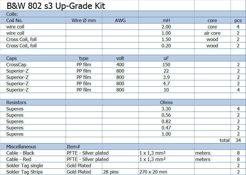
All kit and component prices may be subject to change and are always to be confirmed by Jantzen Audio Denmark.
Download Kit Sale Presentations:

All technical questions to troels.gravesen@hotmail.com
All questions regarding purchase of kits, please mail Jantzen Audio at contact@jantzen-audio.com
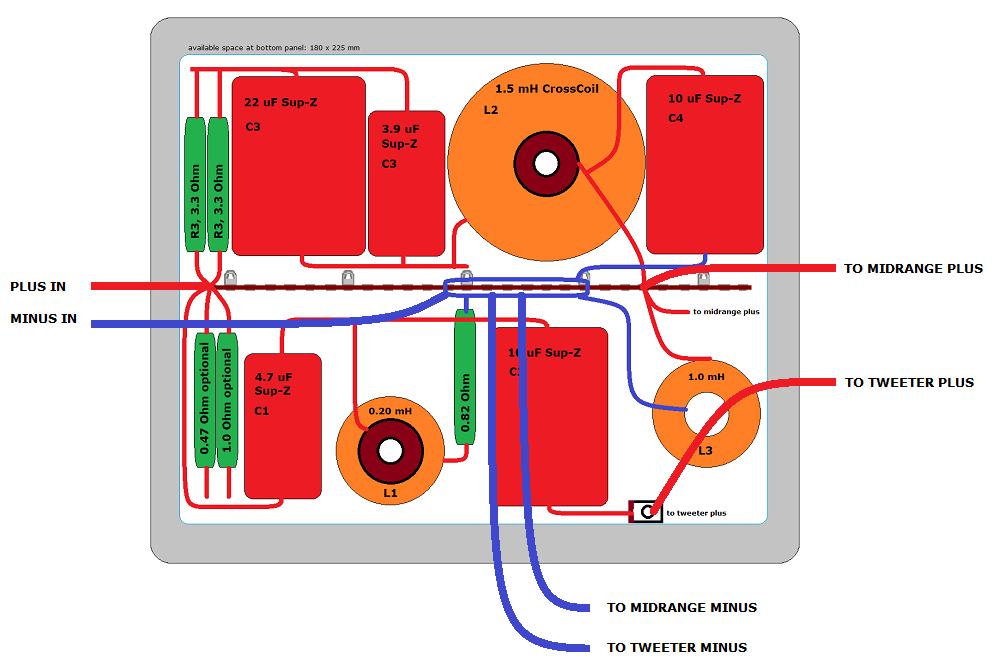
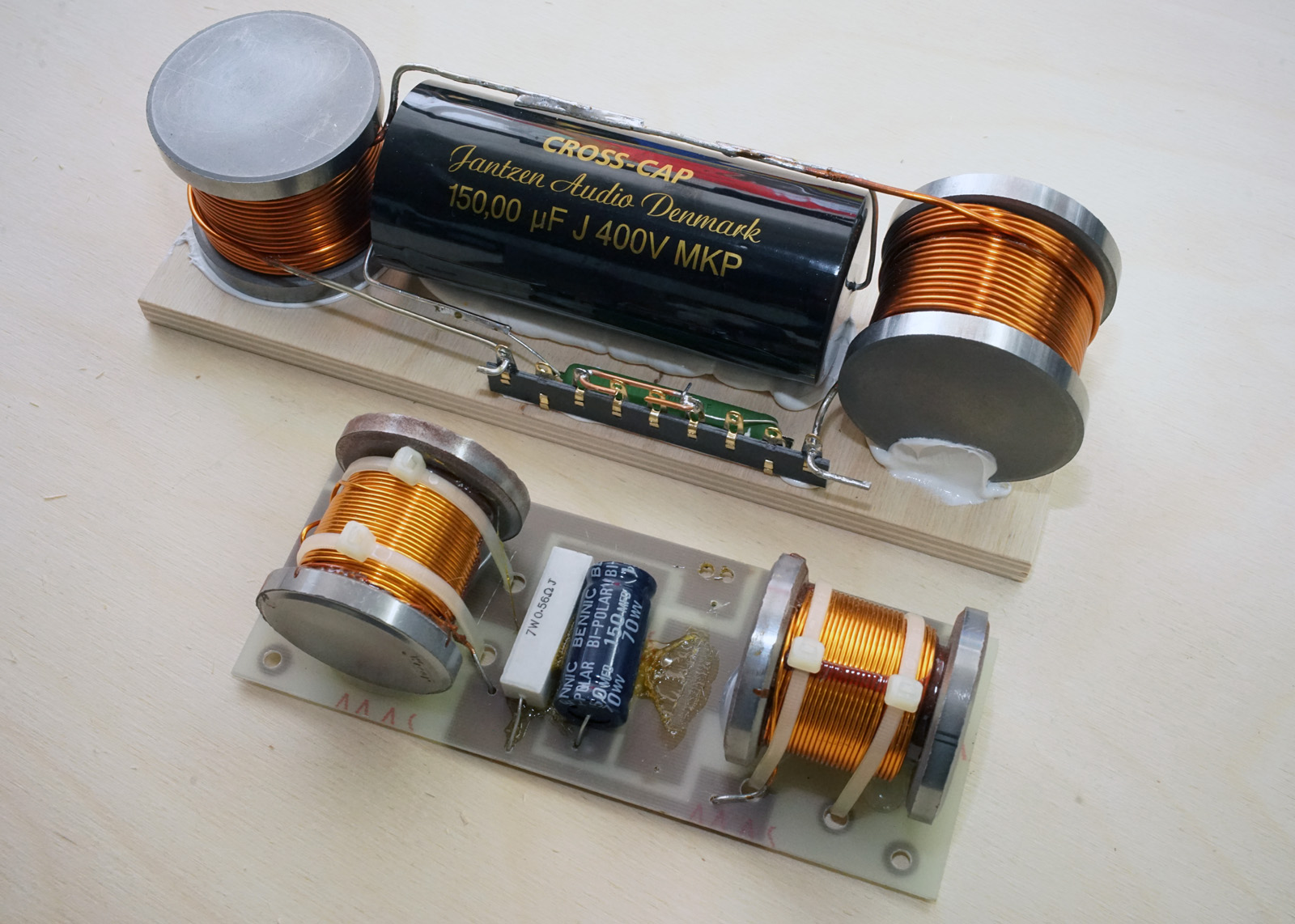
CROSSOVER-LAYOUT
BACK TO INDEX
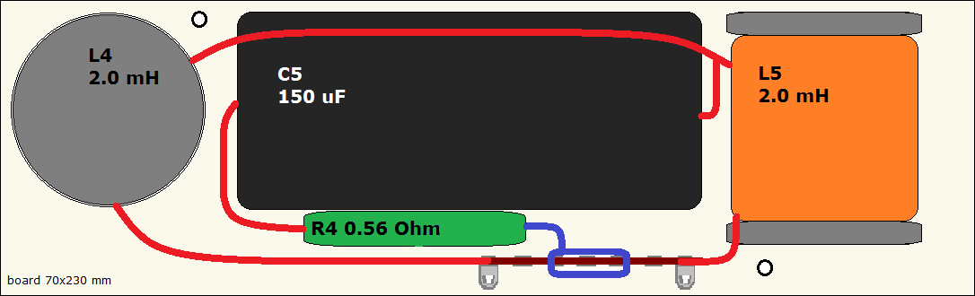
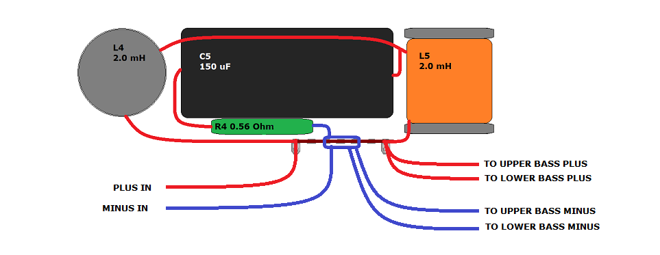
I decided to split the crossover for the sake of space at the bottom and for getting the heavy bass coils as far away as possible from the midrange tweeter section. The bass crossover is placed as seen on photos in between the bracings behind the bass drivers.
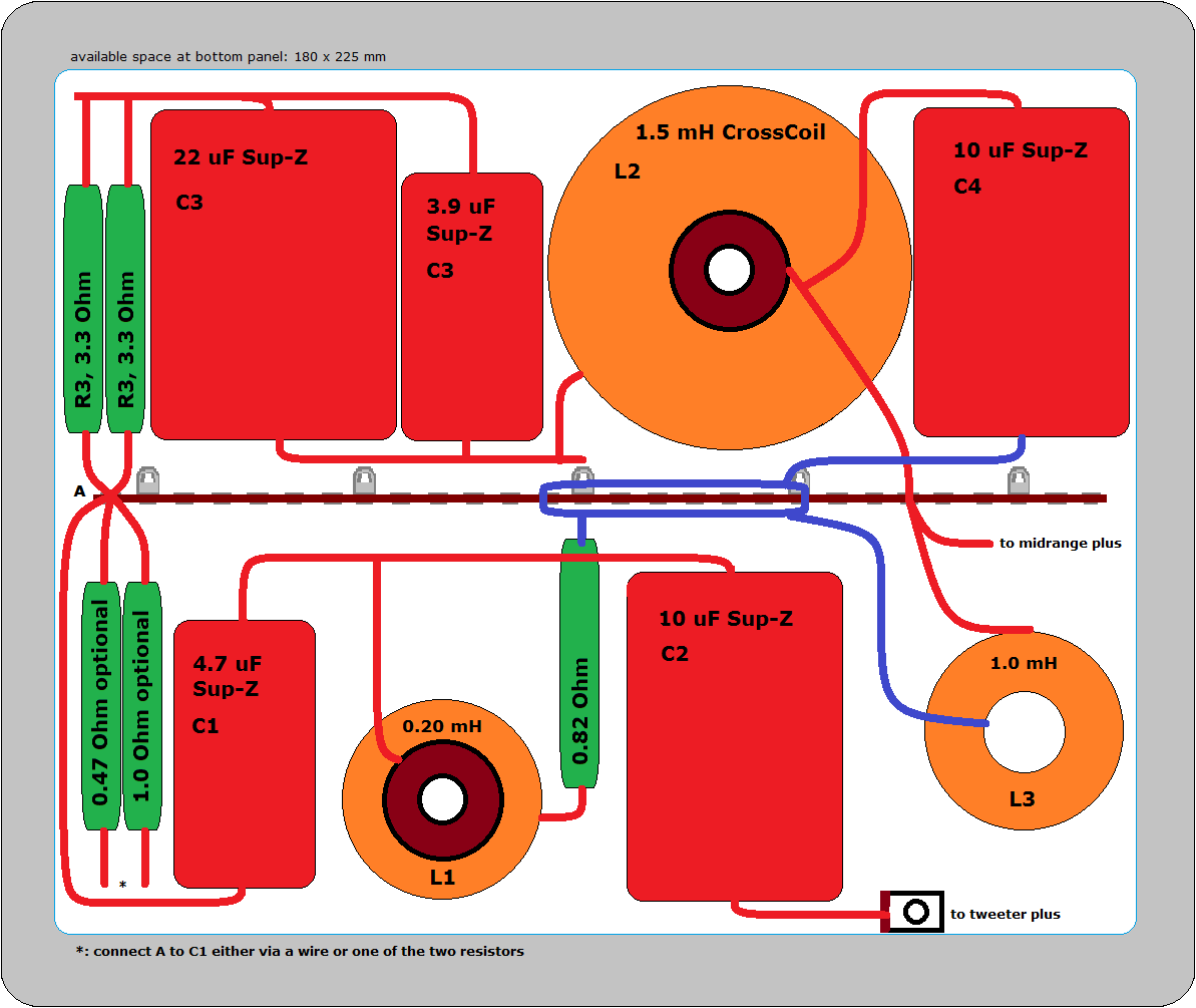
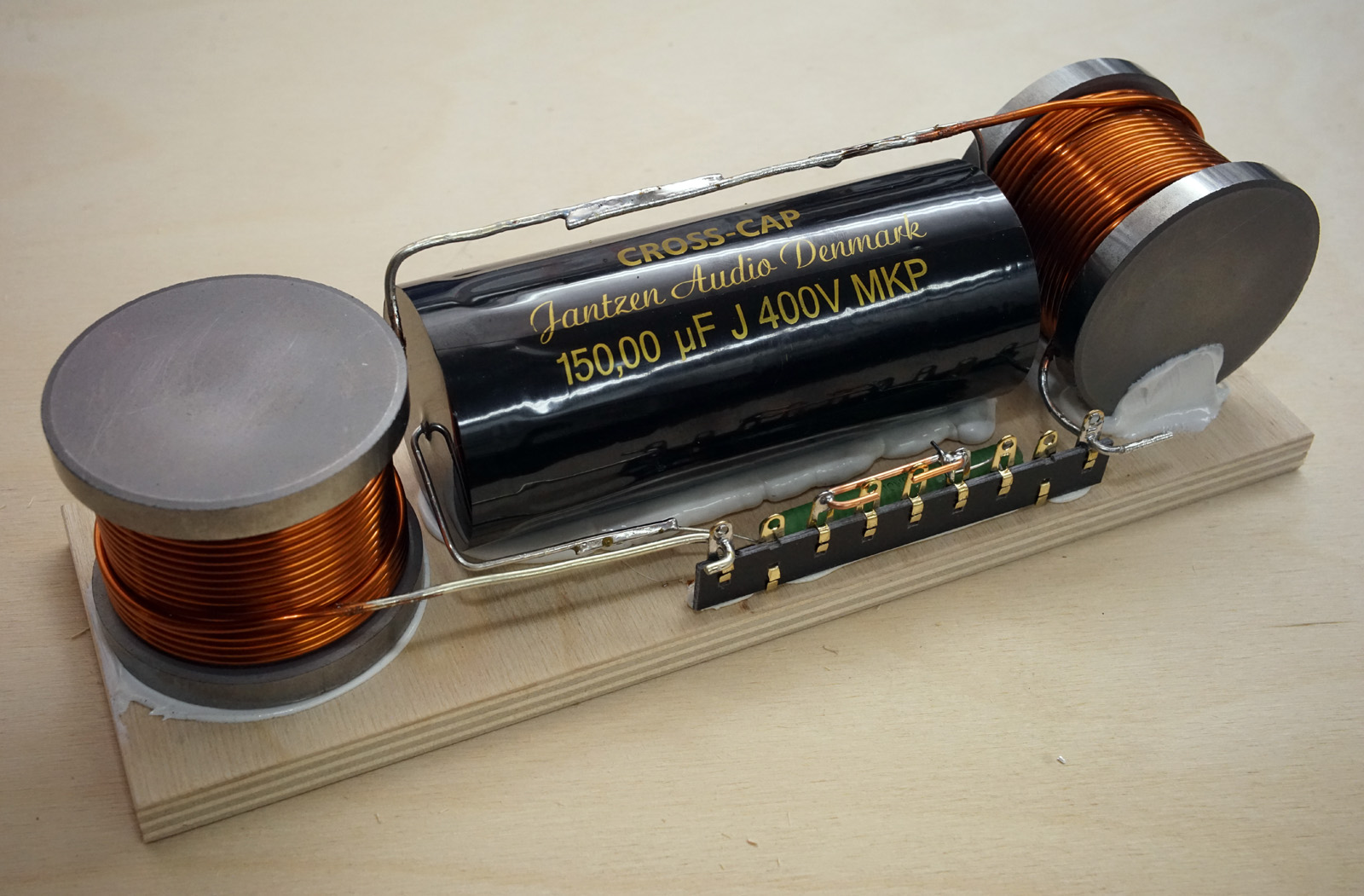
Above crossover board for midrange and tweeter. I have added two optional resistors for tweeter attenuation, 0.47 Ohm or 1.0 Ohm. If you don't want to use these, connect C1 directly to the input point. See wiring below.
I've already commented on the sound in the intro to this article and
what you get from primarily replacing poor electrolytic caps for the
midrange and mediocre BENNIC caps for the tweeter is significant
increase in overall transparency and resolution. The compressed sound of
the electrolytic caps is gone. What stood out from the new crossover was
what I first experienced some 10 years ago when I first tried super
caps, the initial confusing experience of music being darker and
brighter at the same time. The resolution of super caps allows you to
focus on individual aspects of the music in a way poor capacitors don't.
The ability of the speaker to reveal
complex musical signals is enhanced. I obviously compared the measuring
response of the original speaker to the new crossover and only found a
slightly decrease in the 700-800 Hz bump from the new crossover, which
is intentional and due to changed series resistance of L3, as the bump
here in the very important midrange is noticeable from listening to the
original speaker. I've tried not to change the fundamental
voicing of this speaker as some of you may gotten used to this speaker
from many years of service. Hope you enjoy the new crossover as much as
I did.
Wiring
BACK TO INDEX