Vifa C17 mkIV
Copyright
2006 © Troels Gravesen
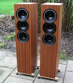  
The C17mk4 on the terrace on a cold and cloudy December's
day, 2006. The oak bars holding the spikes will be black
- some day.
Spikes are Jupiters from Soundcare/Oslo. Great when you
have to move speakers a lot.
Qualifying for
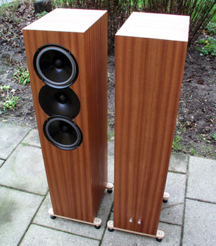
being part of my stock speakers, the
C17s certainly needed some nicer cabs. Some 22 mm
MDF sheets were bought and I took it to my local
veneering company and had mahogany applied. Next
to the veneering company is my local carpenter,
having a table saw at the size of a tennis court,
fitted with a huge saw-blade with uncountable
teeth. Cuts MDF so sharp I usually cut my fingers
bringing it come in my car.
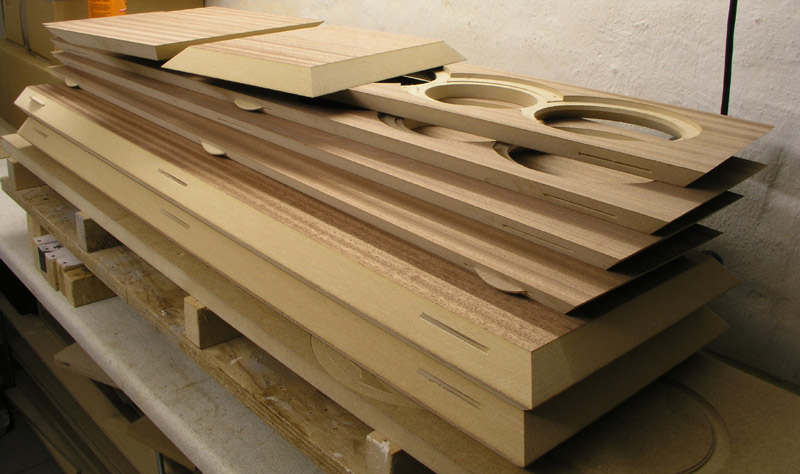
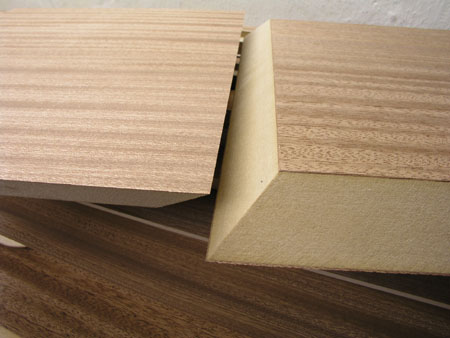
There are pros and cons from this way of making
cabs. The pros are obvious: Perfectly 45 deg. cut
panels that fit exactly when glued together. The
veneering is perfect too, and stays there for
years and years even with the cabs left in the
sun.
The cons are the fragility
of pre-cut panels. From the second you
leave the carpenter's workshop, every single
physical object in the world will try to bump
into the sharp edges and ruin your project.
Getting the panels into the car, getting the
panels from the car into your workshop, moving
the panels a hundred times for routing, etc.,
makes you take a deep breath every time you grab
a panel and it calls for utmost attention all the
time. These razor-sharp edges can drive you nuts.
I bumped a corner on one top panel and had to
apply tiny bits of veneer to rework the corner.
It won't be seen when finished, but knowing it is
bad!
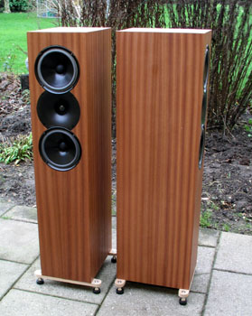
The cabinets
 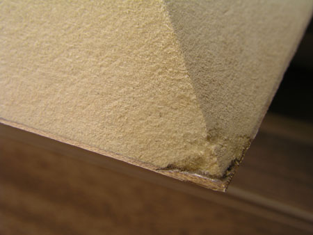
Bumped corner to the right repaired with a tiny piece of
mahogany and some araldite glue.
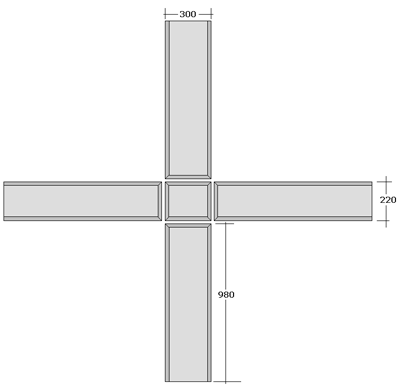
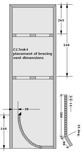
Minor changes were made
to cabs now having outer dimensions of 220 (W) x
300 (D) x 980 (H) mm. The reduced height is due
to making a special vent towards the floor in
order to enhance room-gain and get bit more bass
extension. The cabs will have to be lifted some
40-60 mm from the floor on spikes. Thus, the
depth was increased to 300 mm making a total net
volume of 1.76 x 2.56 x 9.36 = 42.2 litres minus
bitumen pads, braces and the vent. The
exponentially shaped vent is inspired from
reading old Karlson
literature and a couple of not
reported projects have been ahead of this one and
I've found this an interesting way of enhancing
bass performance from optimising room-gain.
 ------------------------
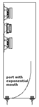
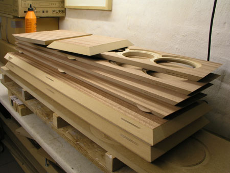
Left: Cutting plan for the carpenter and right:
Vent with exponential mouth.
|
 .jpg)
.jpg) 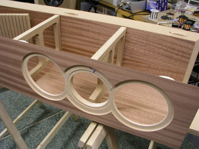
.jpg) 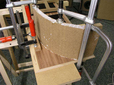
 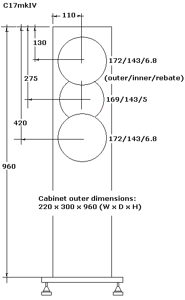
Cabinet
dimensions
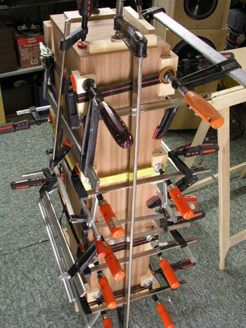
| Cabinet
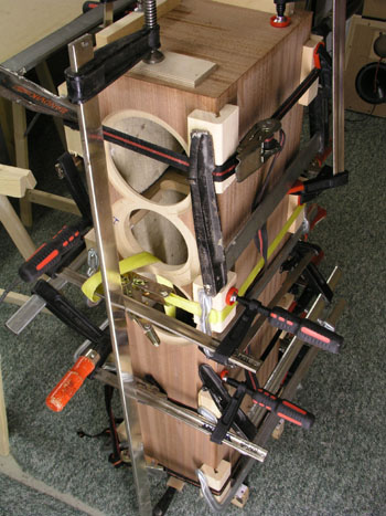
assembly was not as easy as expected. The edges
of the panels are very thin and will easily bend,
so a huge amount of clamps is needed to make the
edges as sharp as possible. Don't use too much
glue and wipe off excessive glue as fast as
possible, otherwise the glue will seal the veneer
and ruin the oil finish. |
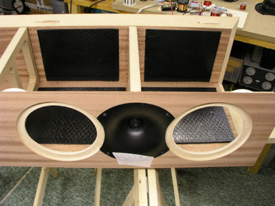
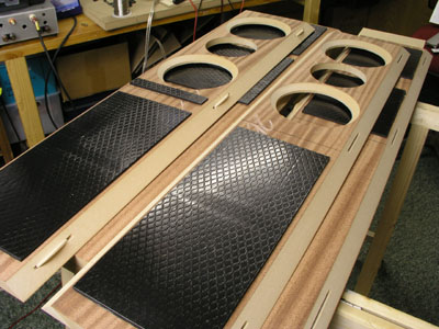
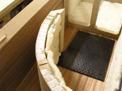
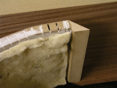
Damping, Monacor MDM3
Two
sheets of MDM3 were stuffed behind the vent at the bottom
to reduce
standing waves between top and bottom.
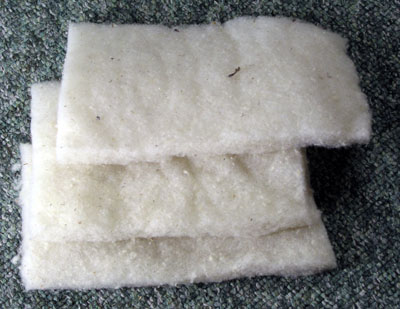 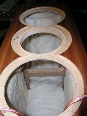
3
pieces of 15 x 35 cm were stacked and attached to rear
panel and top panel behind upper bass driver.
3 pieces of 15 x 25 cm were stacked and added to rear
panel behind lower bas driver.
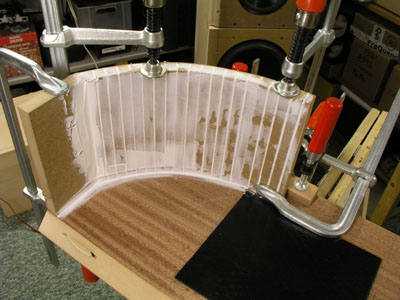
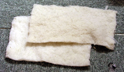
As can be seen, all internal walls were covered with 15
mm pure wool felt material.
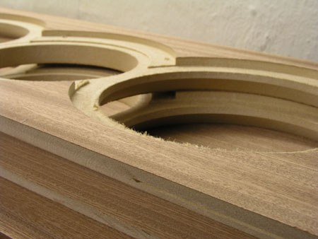
The tweeters:
In order to dampen the waveguide, the cavities were
filled with some acrylic filler. After a few days the
waveguide now feels like piece of MDF.
Blocks of 22 mm MDF were routed and glued to the rear
plastic chamber. In all, the tweeter now seems like rock
solid block. Furthermore the waveguide will be glued to
the front panel. I think all this will pay off. Routing
for the two C17 drivers and the waveguide takes away a
lot of the upper front panel and the damping of the
tweeter + bracing right behind the tweeter will
compensate for the loss of material. Another piece of MDF
will be inserted between the round MDF block and the
bracing behind.
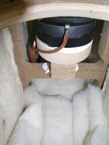
Block of wood between tweeter and bracing.
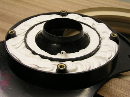
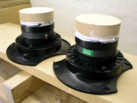
The C17 drivers:
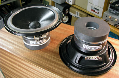
The
C17 drivers were added an additional 90 mm magnet:
Monacor SPM90, item 104260.
The crossover
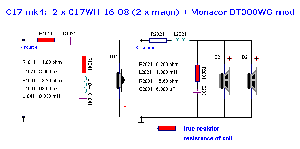
Complete list of
components for two crossovers:
2 x 1R0, 10 W MOX, I was short of 1R0 and used 2
x 2R2 in parallel.
2 x 8R2, 10 W MOX
2 x 5R6, 10 W MOX
2 x 1.0 mH, 0.18 ohm, cross-coil with wax
impregnated paper insulator
2 x 0.33 mH, 0.19 ohm, cross-coil with wax
impregnated paper insulator
4 x 33 uF pp capacitor
2 x 6.8 uF pp capacitor
2 x 3.9 uF pp capacitor, standard or supreme.
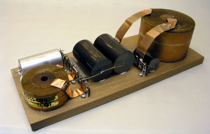
|
Connecting foil coils is
a bit of trouble due to the flat and folded
terminals, but this is how it looks. I also had
some test-samples of supreme caps, here without
the final red wrapping. Thus the huge 3.9 uF
capacitor was used in series with the tweeter. I
guess I can't spoil the C17 set-up much more than
this - well, which should be silver coils, but
the price on silver.....
The boards are 11 x 28 cm and will
be placed on the side panel behind the vent.
|
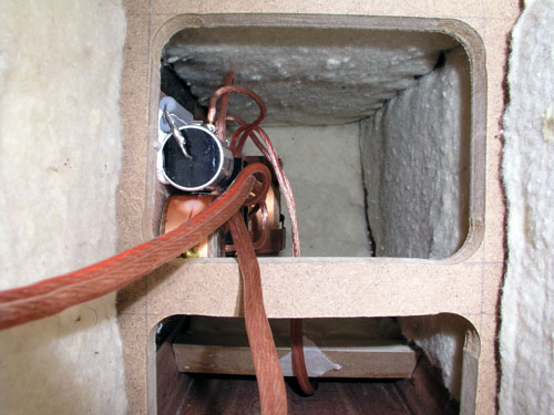
Crossover
attached to side panel behind bottom vent.
Measurements
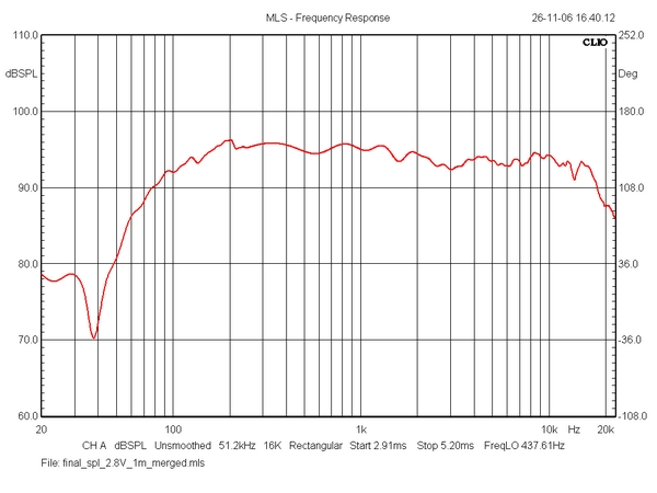
SPL, 2.83 V, 1 m. Merged with nearfield reading @ 250 Hz.
Vent output not included.
Left and right - doesn't get much better than this.
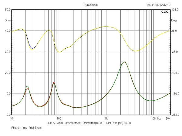
Impedance, left and right speaker.
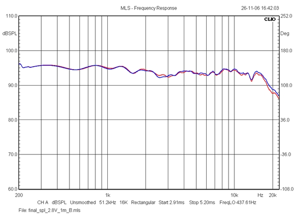
Horizontal dispersion, 0-10-20-30-40 deg.
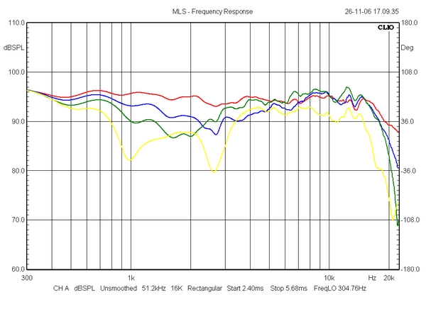
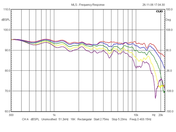
Vertical dispersion. Not surprisingly, a 1st order MTM
doesn't excel here.
Red = tweeter height, blue = + 10°, green = +20°,
yellow = 30°.
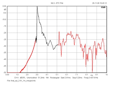 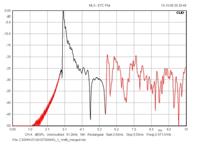
ETC: Left = C17mk4, right
=
C20WH+DT300WG.
Where this construction excels is this ETC plot.
The ETC (energy-time curve) is a tricky measure.
It's calculated from the impulse response and
according to d'Appolito, the ETC is a qualitative
measure of time of arrival. Very useful for
analysing room acoustics, but it also tells
something about time-alignment of drivers and
possible cabinet resonances. A sharp peak
followed by a smooth decline may be an indication
of time-aligned drivers, lack of serious
resonances = stored energy and these two Vifa
constructions appear to excel here. Higher order
filters will store energy as can be seen below.
I've had a number of visitors
recently listening to the current line of
speakers and many have left pointing to this C20,
saying: This is a strange fellow, it
just has something.....
|
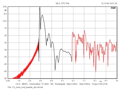 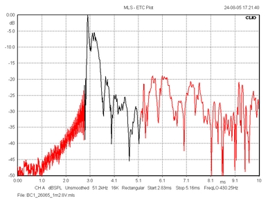
Left
= 2.5 clone, right = Spendor BC1
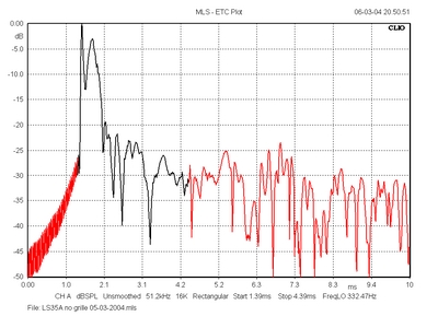

Left
= Rogers LS35A, right = JBL L100 century (not modified).
- the sound....
Well, something must have happened
to the sound from all the changes that have taken place
since my mkIII test-cab version. And so it has.
Initially the idea was to increase sensitivity by adding
extra magnets to the C17 drivers and tuning the
construction for another 1½ dB. It didn't turn out well.
Too much presence and a little too aggressive. Thus the 1
mH coil stayed in place - very much determining the
overall level for the midband. In return the upper bass
and lower mid came with enhanced robustness and solidity.
Placing the vent towards the floor compensates for the
slightly reduced bass due to extra magnet gap flux (=
lower Qt).
So all in all a more firm
presentation in lower registers. The rigid cabinet and
heavy damping appear to pay off in an overall cleaner
sound and the speaker can simply play a little louder
compared to former mk3. Having a 3.9 uF supreme cap (test
sample) I modified the tweeter crossover by lowering the
0.39 mH coil to 0.33 mH to get an overall balance in the
3-7 kHz region like before. The series resistor was
reduced to 1.1 ohm, suggesting there is a small
increase in overall sensitivity of ½-1 dB. Hard to
measure with certainty. The waxed paper-wound coils
appear to do excellent. Having made numerous changes, I
cannot pinpoint the significance of individual changes.
But I'm looking forward to more Jantzen supreme caps
after this one.
The C17 work has been ongoing
for almost half a year - and has been very rewarding. I
dare say that for a modest price you can build a speaker
that will compete with lots of high-end stuff. The
overall level of transparency is extraordinary and for
the size, the bass is deep and powerful. The C17 mk4 will
easily be driven from 20 wpc PSE amps. Even 10 wpc will
do if you do not play too loud.
|