ScanSpeak Discovery-81
Copyright 2022 © Troels Gravesen
Go to on this page:
DRIVERS
CROSSOVER CABINET
WORKSHOP PICS
MEASUREMENTS
SPEAKER-KIT
CROSSOVER LAYOUT
Simplicity has always been a driver in the speaker DIY community. How
little can we get away with and how do we keep cost at a minimum too.
Not always easy because there are compromises in any design.
Back in the Eighties the "8+1" 2-way from Vifa drivers had huge popularity.
I'm thinking of Snell and others. These were indeed very low-cost designs with
el-cheapo tweeters and well, the Vifa C20xx paper cone drivers were
actually really good. Light-weight coated paper cones, 32 mm voice coils, foam surround,
decent magnets and we had quite high sensitivity - at the cost of deep
bass, but this was not of paramount importance to target customers. Also
power handling was compromised due to the small voice coil, but with a 20 watt NAD 3020
everything fell into place.
Now, this Discovery-81 is a very easy construction, maybe the most easy
construction I have ever launched. Due to corona - or other things - kit
sales has sky rocketed over the last couple of years and from mails I
can see there are a lot of first-timers picking constructions they maybe
should not have chosen. You need to consider your skills in woodworking
and basic electronics before engaging, but as said many times, there is
a first time for all. If soldering and woodwork is new to you, this
construction may be a good place to start. Cabinet is as simple as can
be and crossover construction also fairly easy. And I urge you to follow
all the links presented below.
Just because a construction is simple it doesn't necessarily mean the
construction is mediocre. On the contrary, these Discovery drivers will
provide you with a real taste of high-end music reproduction.
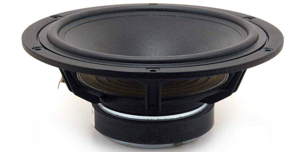
Using an 8" for bass and midrange, even up into the treble range calls
for a very good driver with a decent frequency response and smooth
roll-off. ScanSpeak Discovery 22W/4534G00 does it. Not only does it, but
does it very well. Smooth all the way up to around 4.5 kHz and a
smooth roll-off.
Now, any
driver will start
beaming at a frequency equal to a frequency having a wavelength
equal to the diameter of the radiating cone. The cone diameter of the
22W is 173 mm, thus starts beaming at around 2 kHz, so we need to get
the point of crossover down to 2 kHz and preferably a little below. This
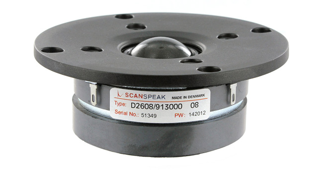
takes a good tweeter, and here we go for the D2608/913000 which due to
the use of magnetic fluid, can handle quite some power and do a low
point of crossover, even from a 2nd order crossover.
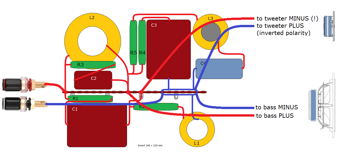
With a large 8" driver doing up to around 1600-1800 Hz we face another problem. Baffle-step loss. Tuning the ~250-600 Hz range reasonably flat, we have a rise in response around 700-900 Hz. This is a common problem and adds a noticeable presence to the sound - great for an acoustic guitar - not so much for vocals and other sources. Like the 8" driver in DTQWT we have to tame this area, hence the LCR circuit seen on schematics. This is very mild equalisation and R5 is quite high and we can get a way with STANDARD-Z for C4 even for level-1. There will be a level 2 with STANDARD-Z caps in all places. This will not give you all what these drivers can deliver, because they can deliver a lot, but some people just don't believe in super-caps. The result from standard PP caps is some loss in overall resolution and smoothness of treble.
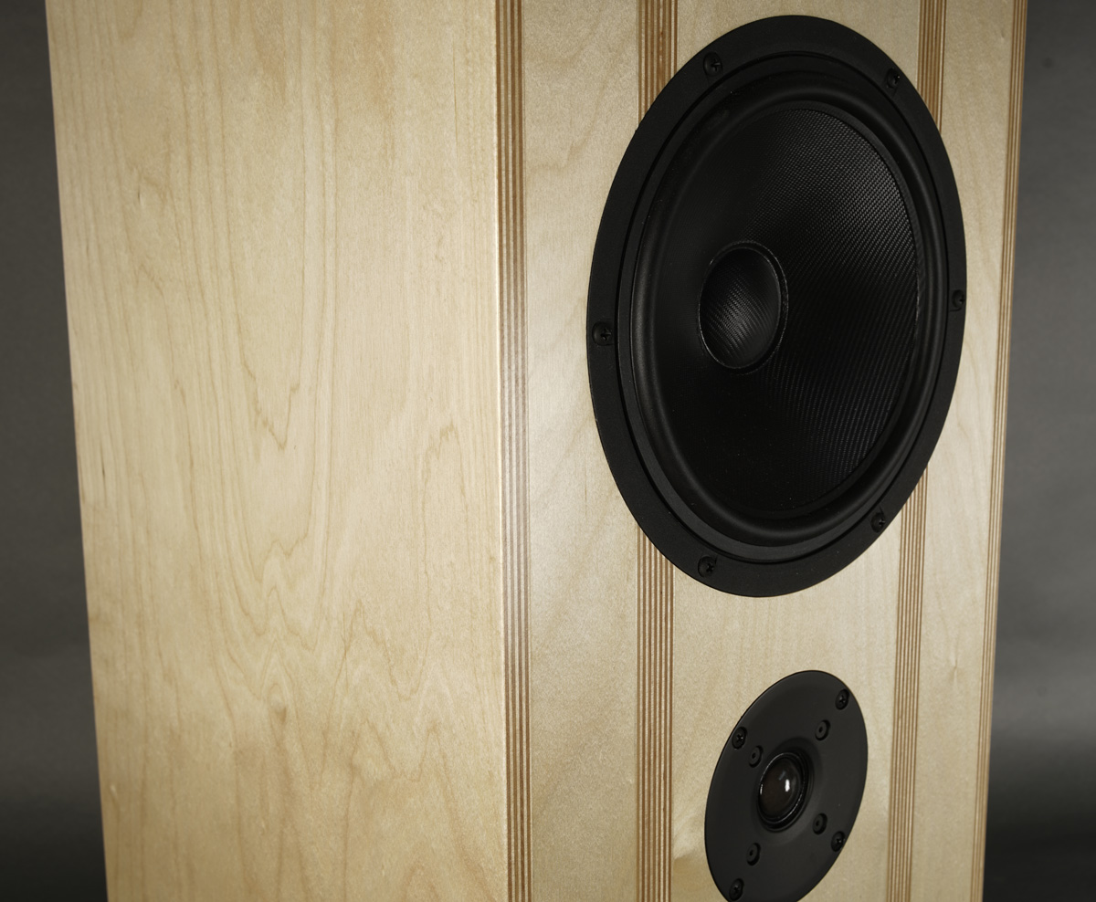
Time-alignment is an issue with an 8" in a 2-way, hence the 22W on top and this is the optimum listening height. Adjust support to match you listening height. From my couch, some 40 cm will bring the 22W at ear-height.
The 4 Ohms midbass driver will provide you a system sensitivity of around 90 dB and a benign impedance making it an easy load for even smaller amplifiers. Minimum 20 wpc is recommended. I've used my 15 wpc EAR-869 amp without trouble.
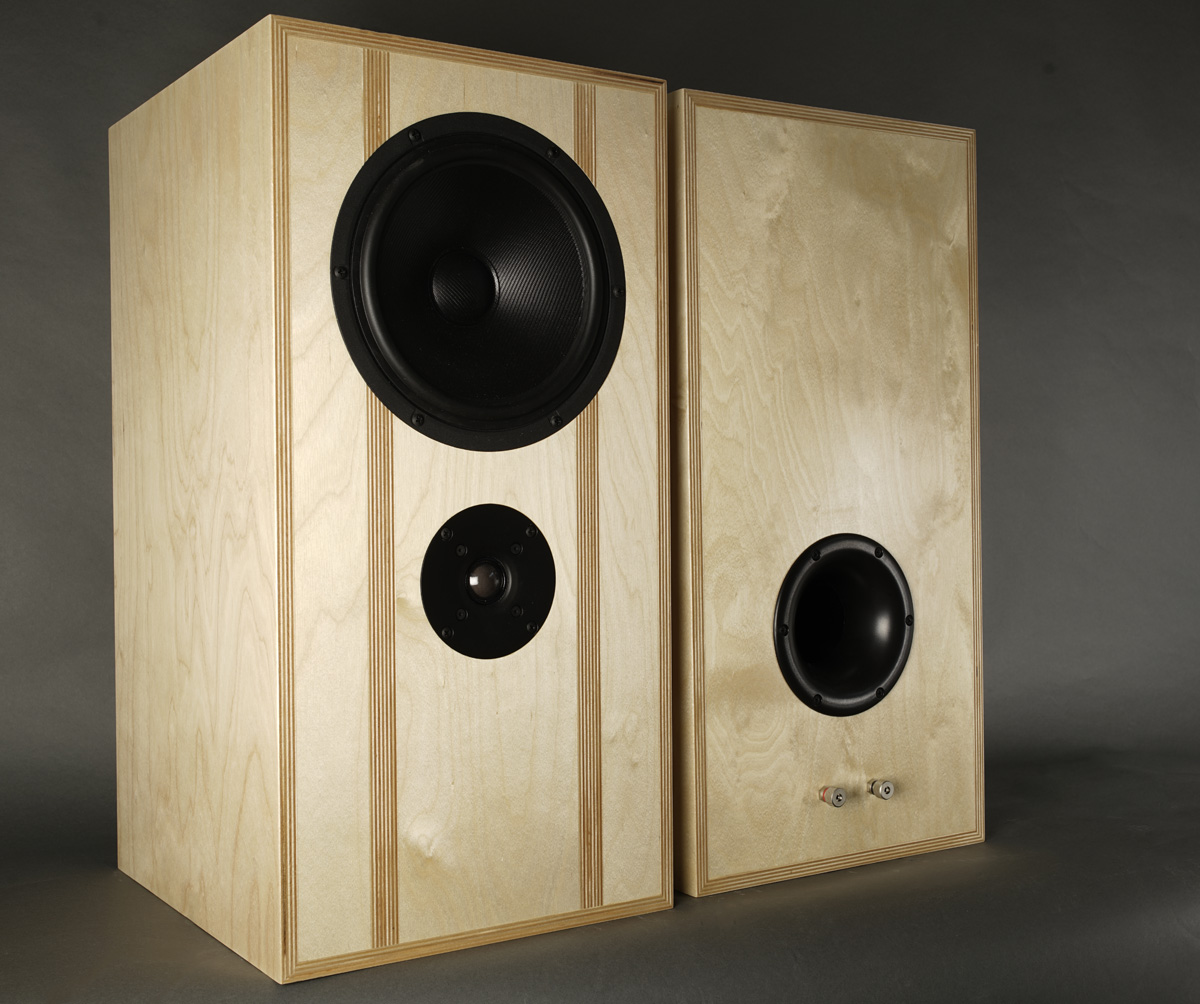
Sound? Well, only thing I can say that having a great 8" mid-bass driver without any point of crossover in all of the bass and midrange leaves an astonishing level of transparency with an overall smooth transition to the tweeter.
Basics:
2-driver speaker.
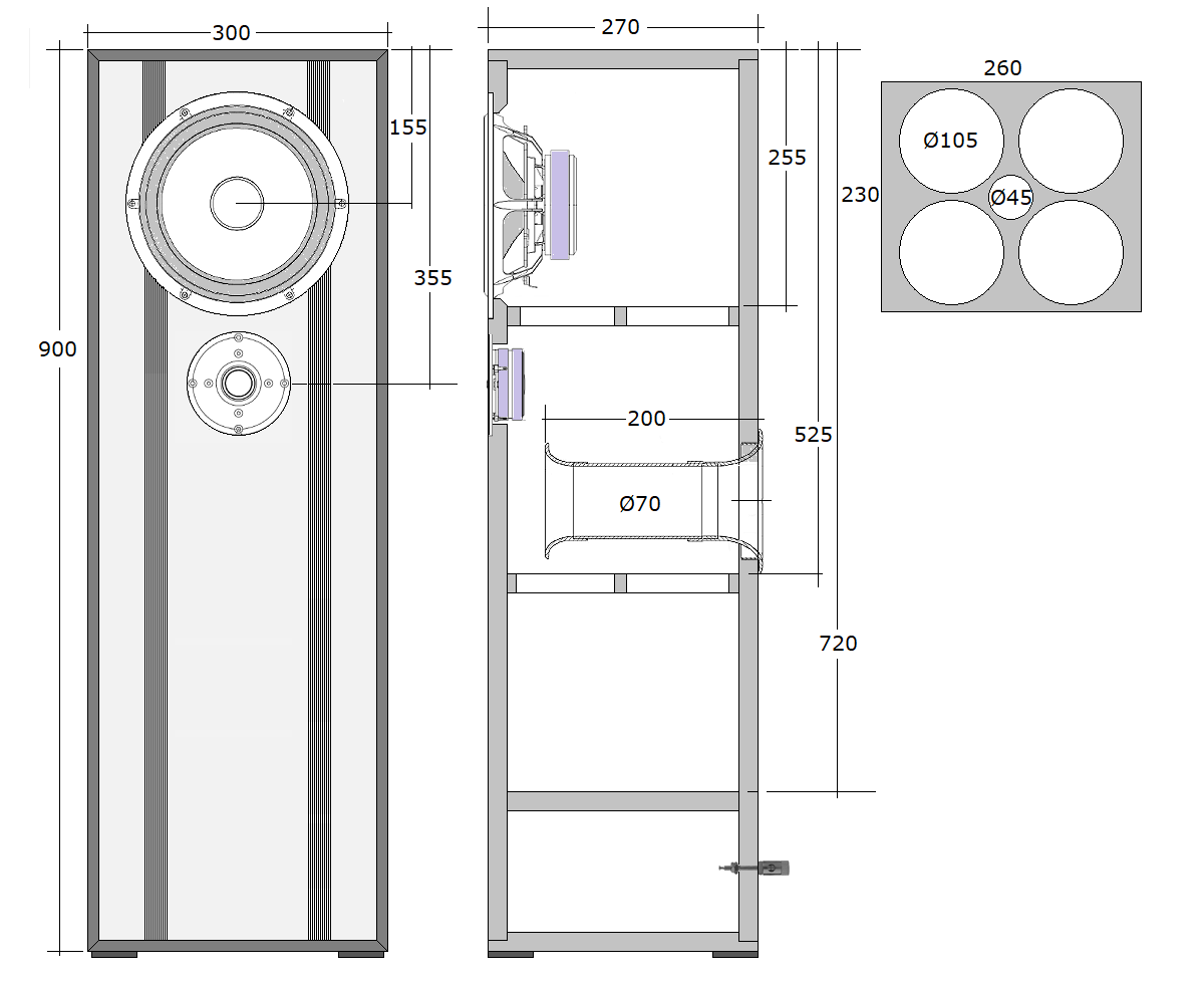
Dimensions: 30 x 35 x 60 cm, WxDxH.
System sensitivity: 90 dB/2.8V/1 meter.
Impedance: 4-8 Ohms.
Power requirement: 20+ watts/channel.
Power handling: 100 watts.
Please
also read:
http://www.troelsgravesen.dk/power-handling.htm,
and remember any burned driver is a misused driver.
Useful links (Please
follow all links before e-mailing!):
http://www.troelsgravesen.dk/tips.htm
http://www.troelsgravesen.dk/tips.htm#CONSTRUCTION_OF_CROSSOVERS
http://www.troelsgravesen.dk/crossovers.htm
http://www.troelsgravesen.dk/LCR-RC.htm
http://www.troelsgravesen.dk/Inverted-Polarity.htm
http://www.troelsgravesen.dk/choices.htm
http://www.troelsgravesen.dk/power-handling.htm
PLUS
Download specs here: D2608/913000 22W/4534G00
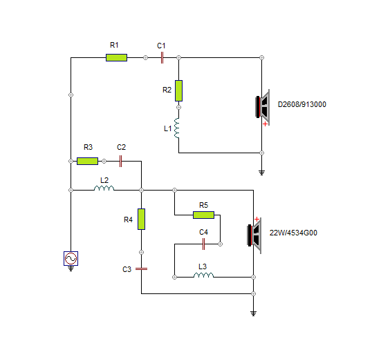
The crossover features a simple 2nd order topology with an LCR circuit (R5+C4+L3) handling the 600-1200 Hz area to a smooth midrange. Point of crossover around 1800 Hz.
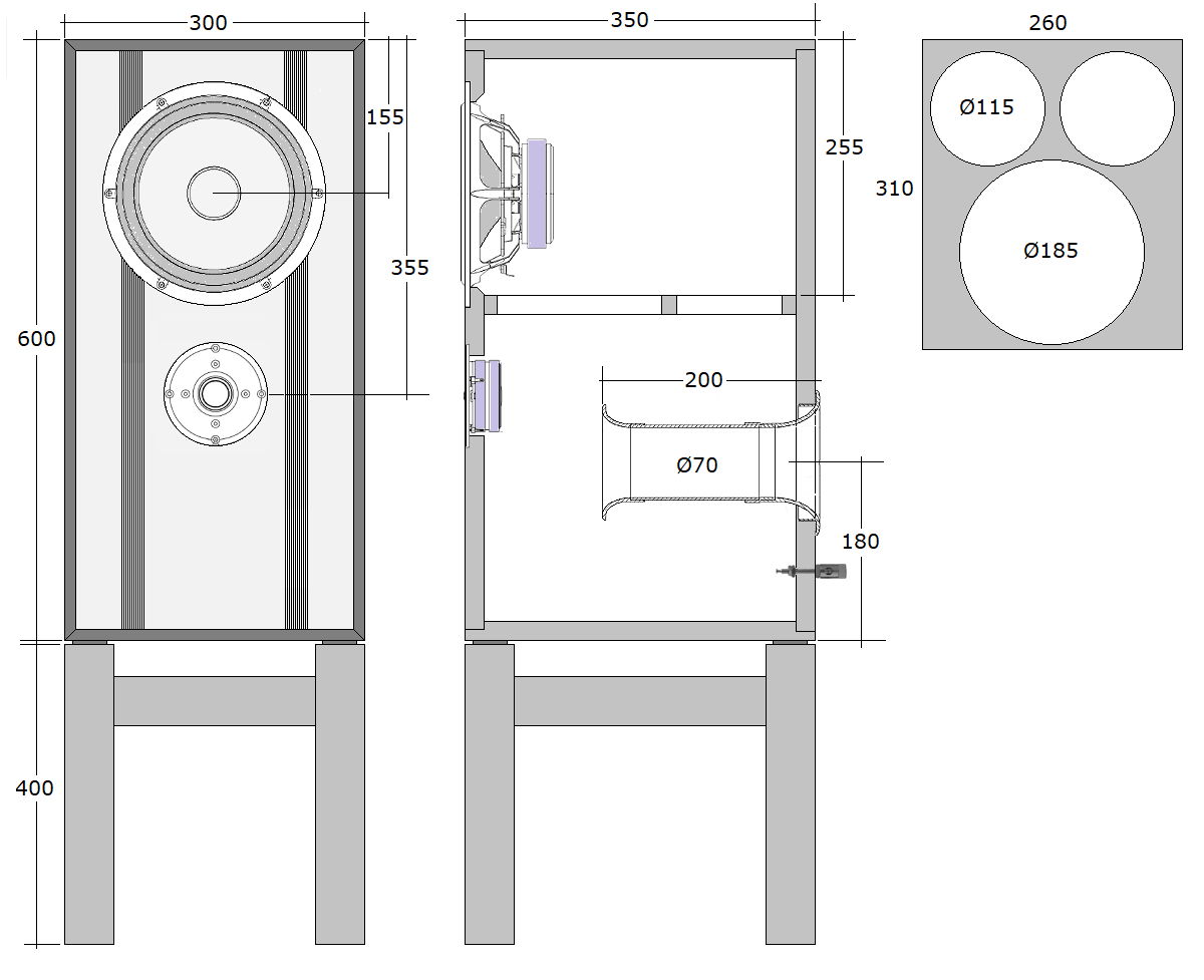
Cabinets made from 20mm Baltic birch. Alternatively use 19-22 mm MDF/HDF
and stick to outer dimensions.
I'm sure I'll have the question of doing a floorstander rather than a
stand-mount, and yes, you can do that by reducing depth, but make sure
the port can breathe and you may have to raise the bottom floor of the
cabinet to keep volume of ~45 litres. And yes, 43-47 litres is fine. Too
little difference to matter.
You don't have to rebate baffle sides and top/bottom as shown on
drawing. A simple basic butt joint is fine.
Should you want a floor-stander, go to bottom of page.
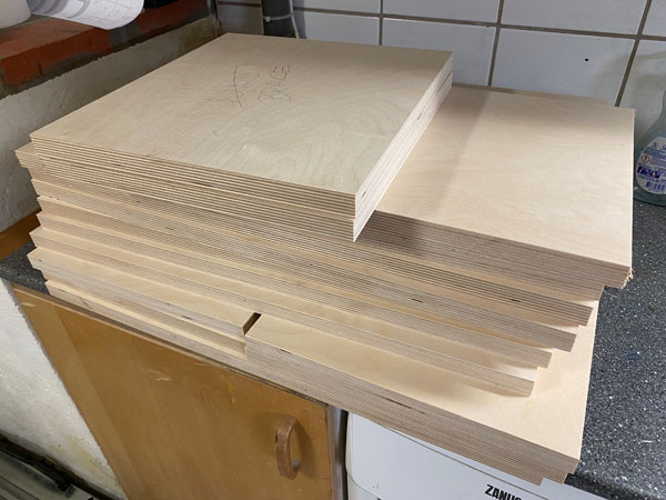
To the left all panels in the rough, cut some +1 cm length and width.
After this panels are sanded and given the first coat of lacquer. This I
always do to prevent panels sucking up wood glue that penetrates the
outer veneer layer and eventually leave light spots after the final
coats of lacquer. Once I have made the rebates, I sand the edges and
apply a coat of lacquer here also.
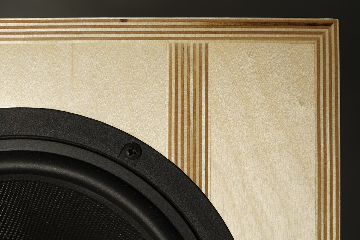
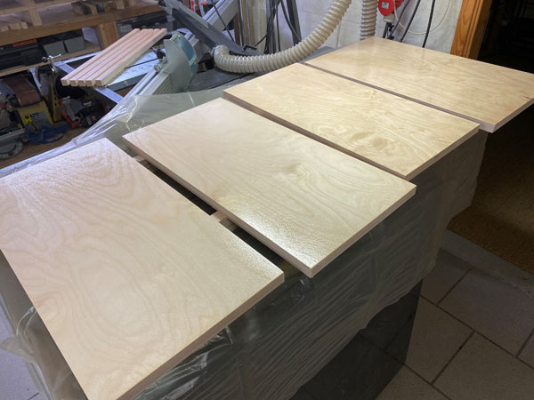
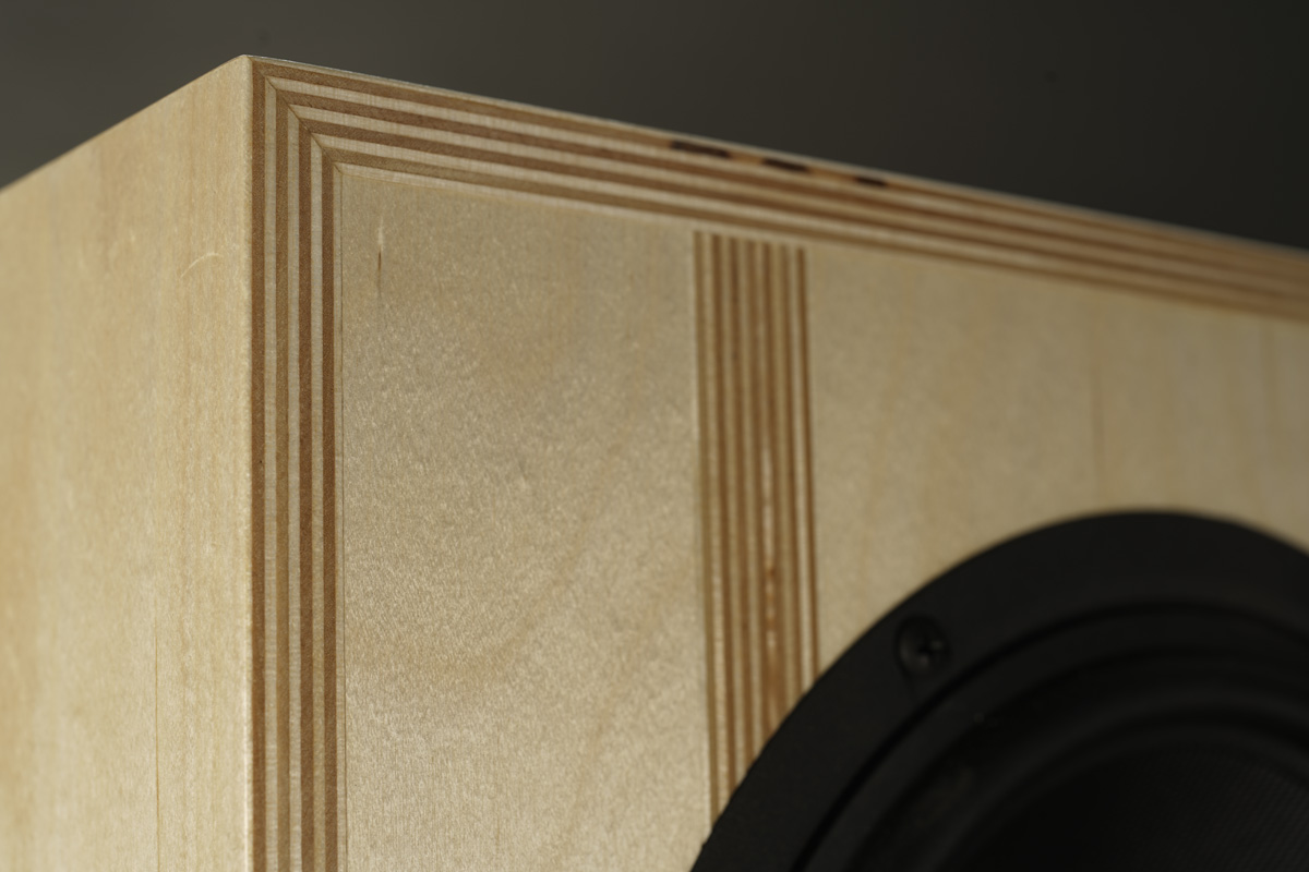
Cabinet panels almost ready for gluing.
And no, the panels are NOT made from a laminate. What you see is the
rebates.
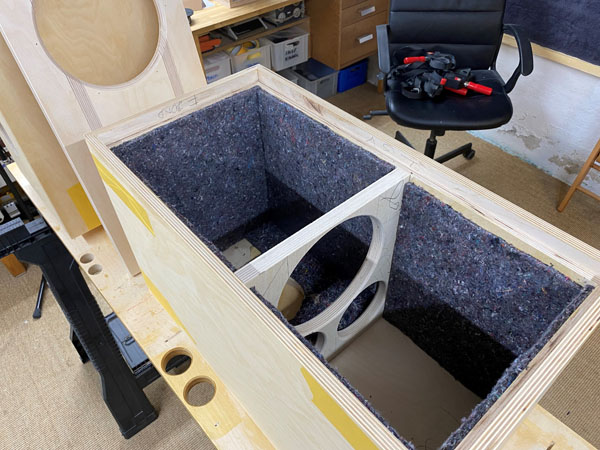
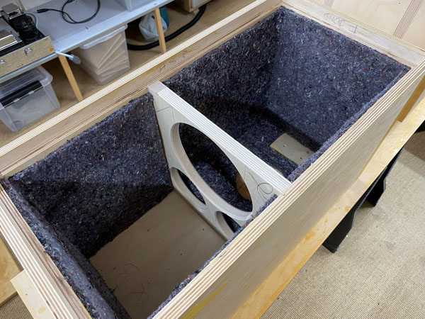
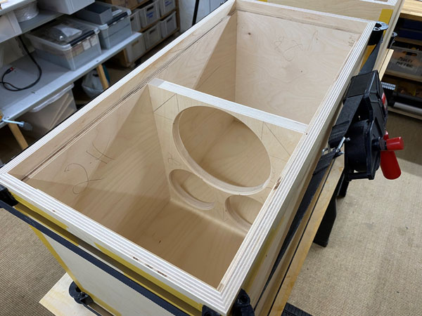
All felt pads in place. Acoustilux comes
later.
No felt on rear panel where the crossover is to be placed and covered
with Acoustilux.
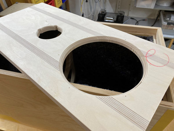
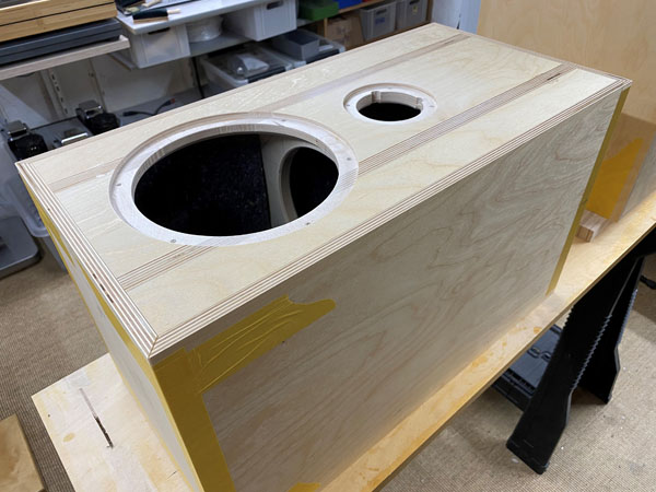
Chamfer the 22W driver holes slightly, 6-8
mm, 45 deg. Cabs now ready for gluing.
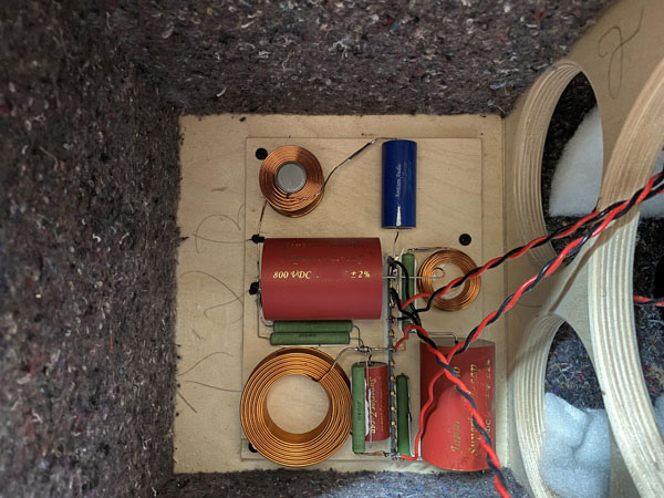
Place the crossover on rear panel behind 22W driver.
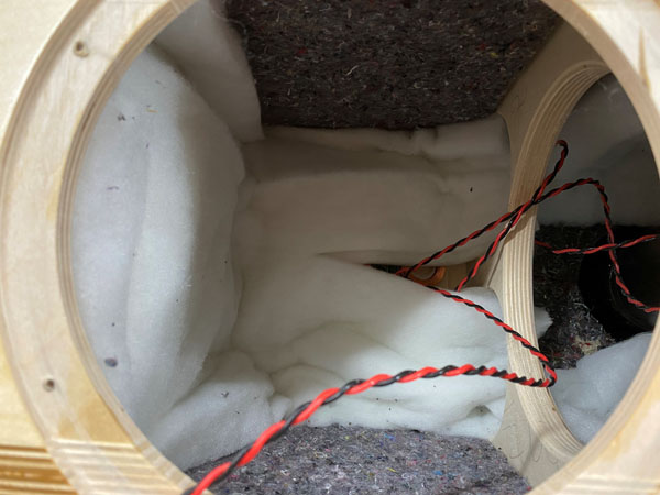
Acoustilux damping.
For one cabinet:
1: Fold a piece of 27 x 50 cm and place on bottom of cabinet.
2: Cut 2 pieces of 25 x 50 cm and place on sides and front of bottom
section of cabinet. Upper picture to the right.
3: Cut 2 pieces of 27 x 50 cm, stack the sheets and slice to allow wires
from the crossover, upper picture to the left.
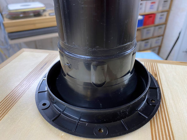
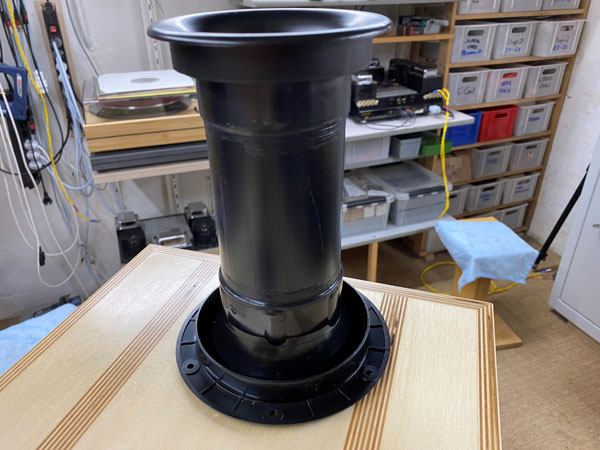
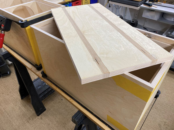
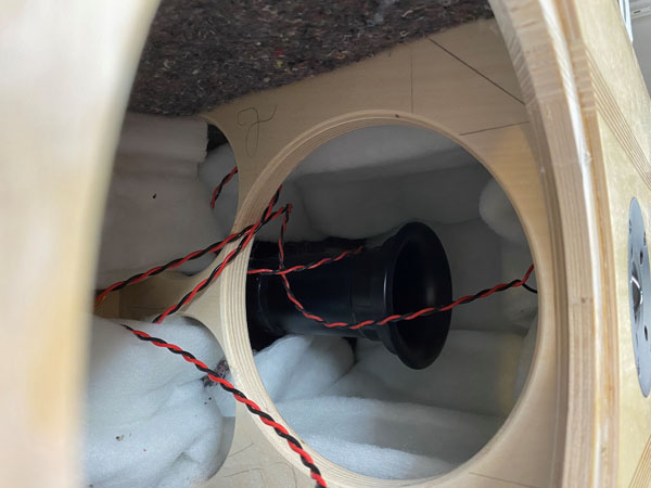
Gluing the port.
A few comments on
MEASUREMENTS before you start interpreting the readings below.
First of all, if we think measurements will
tell us how a speaker sounds, we're wrong. The perception of sound is
way too subjective to be reflected in any measurements we can perform. A
loudspeaker system is meant to give us a satisfying idea of an acoustic
event and for some people a pair of 5 USD ear-plugs are enough, others
spend 200 kUSD on a truly full-range pair of speakers - and the latter
may not be happier than the former.
Measurements may give us an idea of tonal balance of a system, i.e. too
much or too little energy in certain areas, although dispersion
characteristics play a vital role here. A two-way 7+1 and a three-way
7+4+1 may display similar horizontal dispersion, yet sound very
different. Measurements may tell us about bass extension if far-field
measurements are merged with near-field measurements. In addition to
this, ports may contribute to bass extension. Most of we diy'ers do not
have access to an anechoic room for full-range measurements from
20-20000 Hz.
What cannot be seen is what kind of bass performance we get in a given
room. Bass performance is highly dependent on in-room placement of your
speaker and the same speaker can be boomy in one place and lean in
another. Actual SPL level at 1 meter distance and 2.8V input is useful
for en estimate of system sensitivity and combined with the impedance
profile may give an idea of how powerful an amplifier is needed to drive
the speaker to adequate levels.
What measurements do not tell is the very sound of the speaker unless
displaying serious linear distortion. The level of transparency, the
ability to resolve micro-details, the "speed" of the bass, etc., cannot
be derived from these data. Distortion measurements rarely tell much
unless seriously bad, and most modern drivers display low distortion
within their specified operating range.
Many people put way too much into these graphs and my comments here are
only meant as warning against over-interpretation. There are more to
good sound than what can be extracted from a few graphs. Every graph
needs interpretation in terms of what it means sonically and how it
impacts our choice of mating drivers, cabinet and crossover design.
What measurements certainly do not tell is the sonic signature of the
speaker, because speaker cones made from polypropylene, aluminum,
Kevlar, paper, glass fiber, carbon fiber, magnesium, ceramics or even
diamonds all have their way of adding spices to the stew. Nor do
measurements tell what impact the quality of the crossover components
add to the sound, from state of the art components to the cheapest of
coils and caps, they all measure the same if values are correct, yet
sound very different.
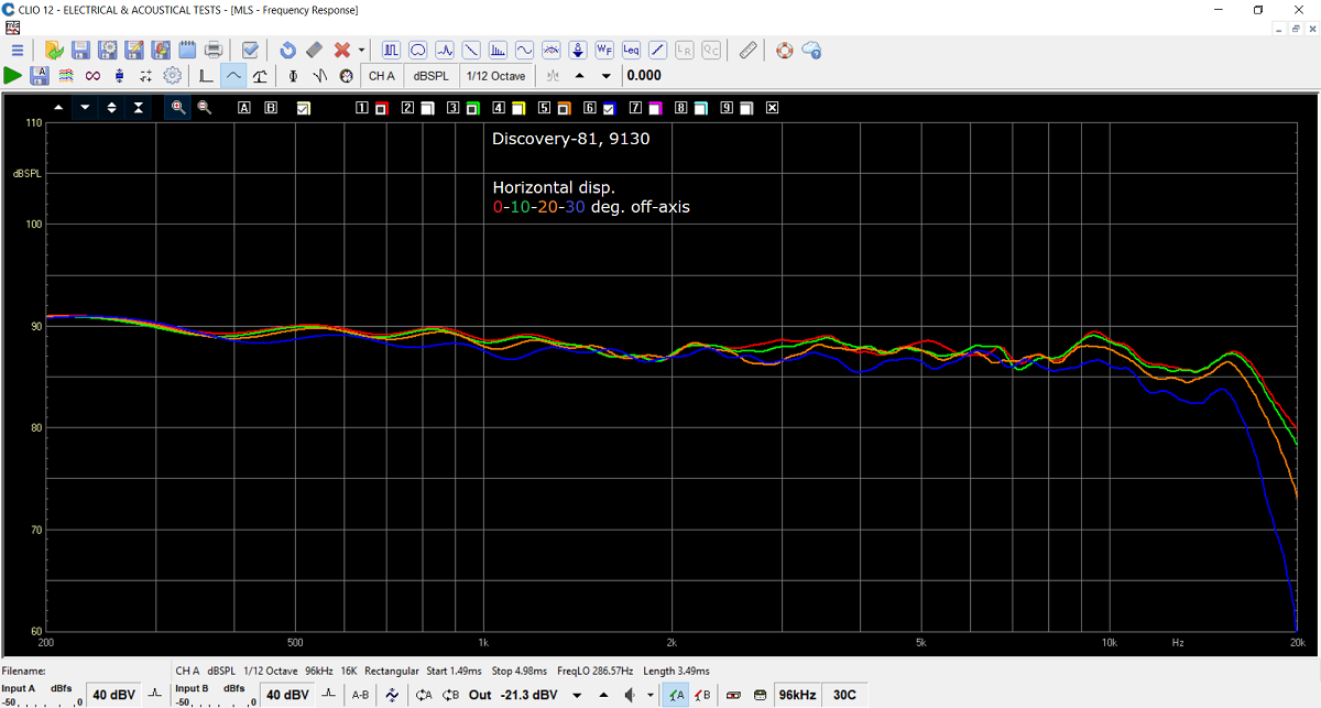
Above horizontal dispersion @ 0-10-20-30 deg. off-axis.
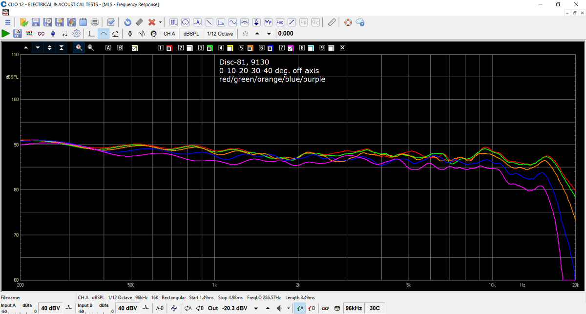
Here 40 deg. included, Quite interesting as
the midbass here shows its limitations, albeit very little at an extreme
angle.
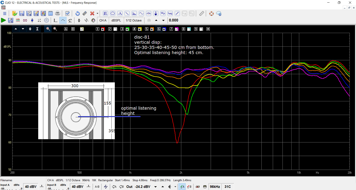
Vertical dispersion is something almost never
shown for multiway systems. Why? Because they never look good due to
crossover lobing.
As can be seen optimal listening height is around the midbass center.
The value of these measurements are arguable as what the microphone may
pick up at a given height at short distance (here 0.5 meter) is hardly
what we will hear when sit on our couch or move around the room.
But this just to show the reason for having the midbass on top - and
believe me, if you can persuade your brain not to be preoccupied, then
you cannot hear the treble is placed below the midbass. If it disturbs
your visual pleasure, add a front grill.
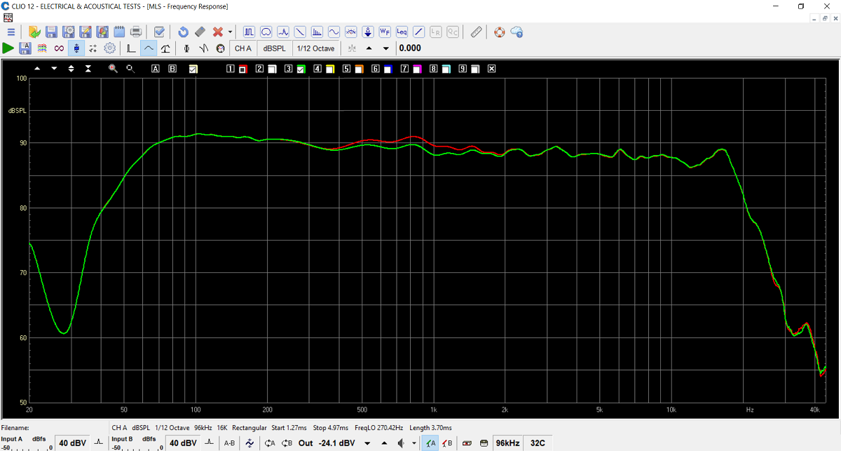
Here the impact of the midrange notch filter.
It doesn't look of much, but believe me, it does its thing.
You can try it without and hear what happens.
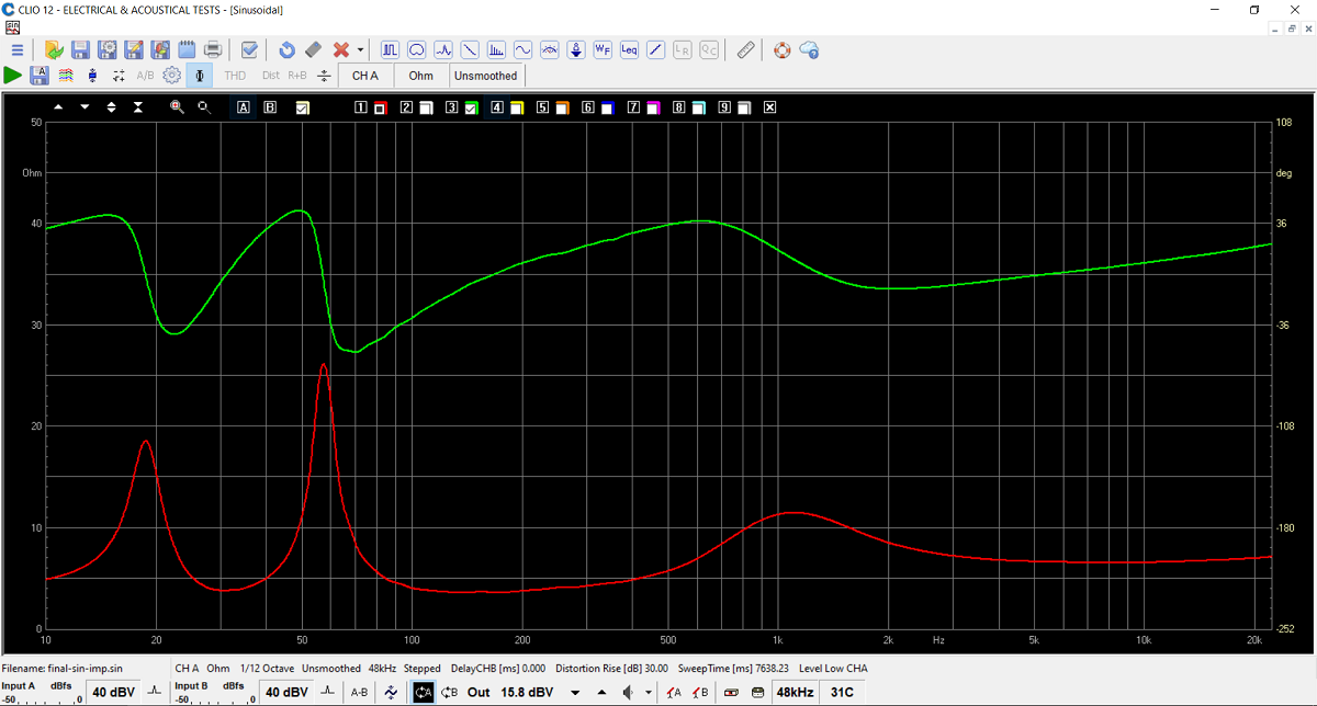
Final system impedance. Quite an easy load.
Minimum 3.5 Ohms @ 135 Hz.
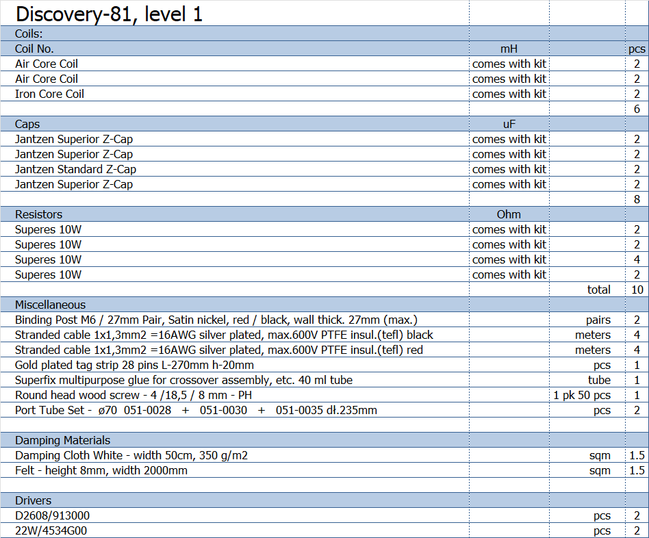
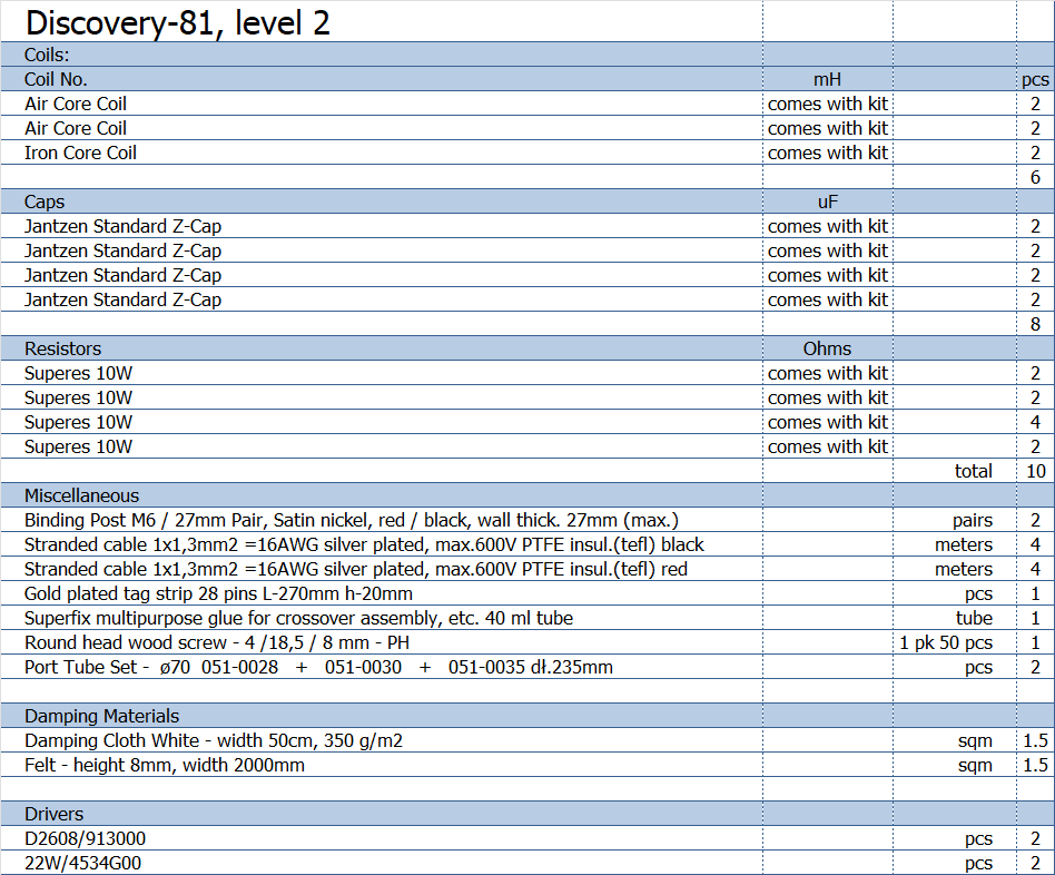
All kit and component prices may be subject to change and are always to be confirmed by Jantzen Audio Denmark.
Kits can always be bought with/without drivers, or some of the drivers.
Download Complete Kit Sale Presentations:
![]()
All technical questions to troels.gravesen@hotmail.com
All questions regarding purchase of kits, please mail Jantzen Audio at contact@jantzen-audio.com
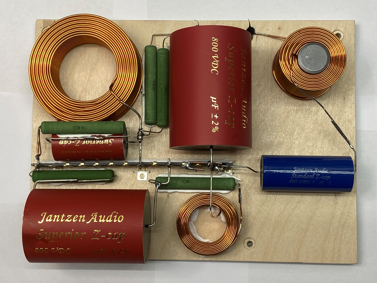
CROSSOVER-LAYOUT
BACK TO INDEX
Check this out before start making crossovers:
http://www.troelsgravesen.dk/tips.htm#CONSTRUCTION_OF_CROSSOVERS
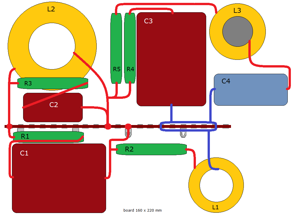
Cut the solder tag strip in two.