ScanSpeak Discovery
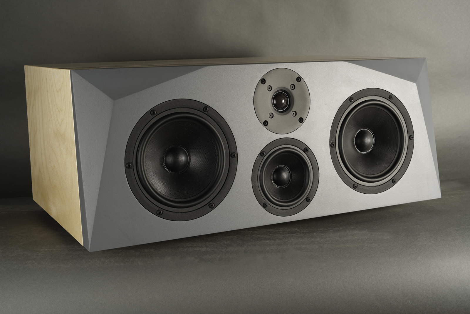
CENTER
Copyright 2023 © Troels Gravesen
Go to on this page:
DRIVERS
CROSSOVER
CABINET
MEASUREMENTS
SPEAKER-KIT
CROSSOVER LAYOUT
A ScanSpeak center speaker has been on the to-do list for a long time,
so here it is. Initially I was thinking of Illuminator drivers, but
my recent experience the
Discovery-861, convinced me of using the Discovery drivers as they
offer exceptional performance. I wouldn't hesitate to use this center
speaker with the Ekta-mkII, The Ekta Grande, Ekta-25 or any middle sized
floor-stander or the 3-way classics, being ScanSpeak or other brands.
Some may think my use of crossover components' quality is extravagant,
but these drivers deliver when fed an undistorted signal. Worth every
cent. Eventually there will be a low-cost version with STANDARD-Z caps
for the midrange and Superior-Z for tweeter.

Click images to view large.
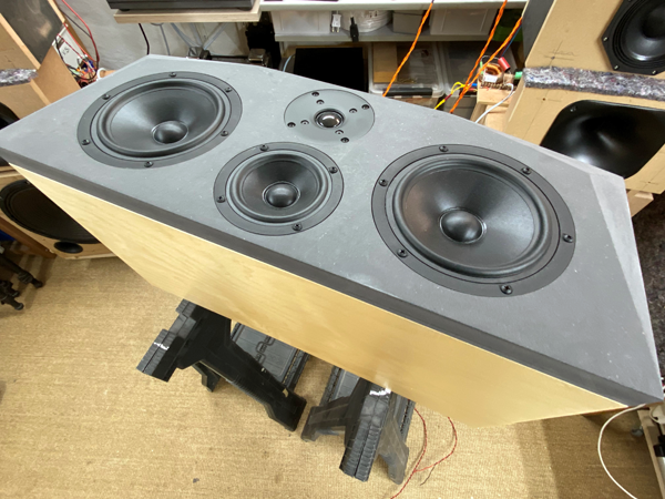
Basics:
4-driver speaker
Dimensions: 65 x 38 x 25 cm, WxDxH.
System sensitivity: 89 dB/2.8V/1 meter.
Impedance: 4-8 Ohms.
Point of crossover: 600 and 2600 Hz.
Power requirement: 20+ watts/channel.
Power handling: 100 watts. Please
also read:
http://www.troelsgravesen.dk/power-handling.htm,
and remember any burned driver is a misused driver.
Useful links (please read before writing!):
http://www.troelsgravesen.dk/tips.htm
http://www.troelsgravesen.dk/crossovers.htm
http://www.troelsgravesen.dk/LCR-RC.htm
http://www.troelsgravesen.dk/choices.htm
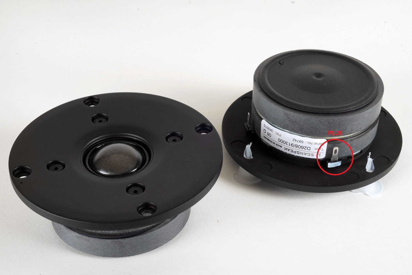
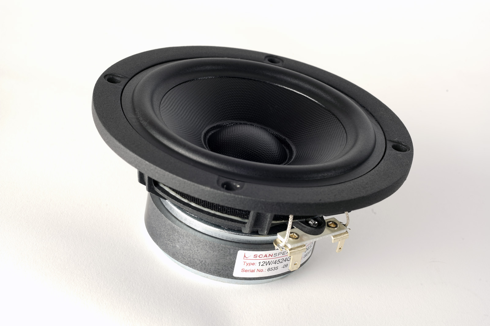
Click images to view large
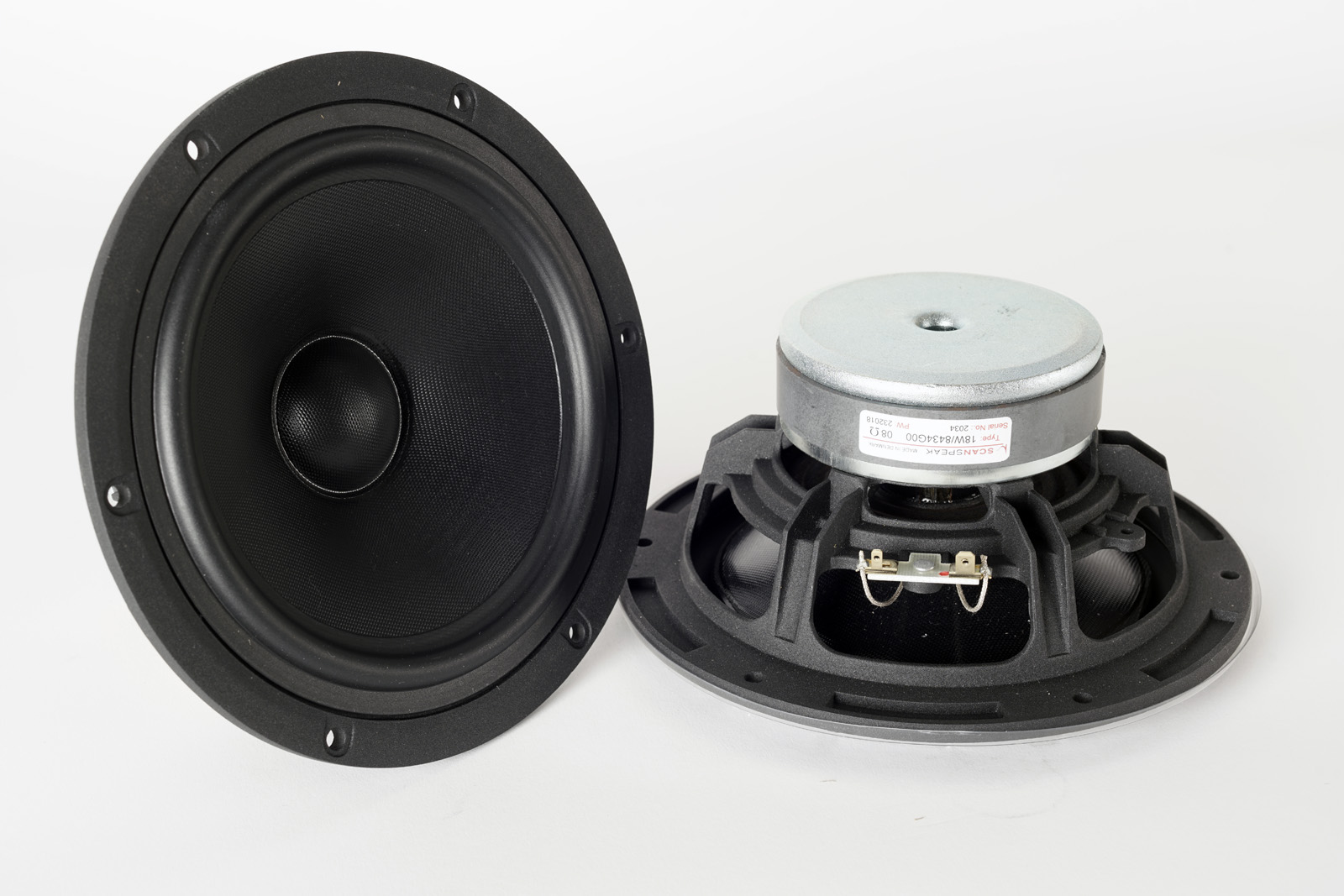
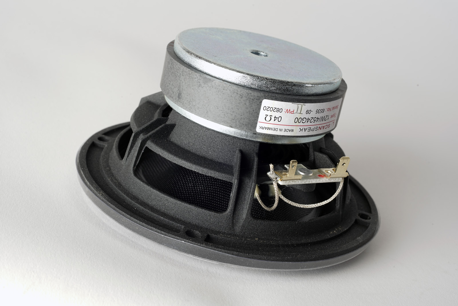
Download specs here: D2608/913000 12W/4524G00 18W/8434G00

Pay notice to the two 18W/8434G00 drivers being connected in series. The 18W is quite efficient and even with the 8 Ohms version being use here, we have to use the 12W in 4 Ohms to match efficiency.

Click drawing to view large
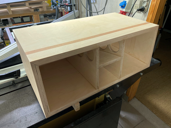
Cabinets were made from 20 mm Baltic birch and bracing/mid-cab/port from
15 mm BB. Front panel I made from 25+10 mm black MDF (HDF). I
suggest 19-25 mm.
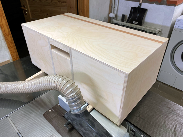
The
chamfering of the front panel is optional, but I think it looks cool..
Workshop images
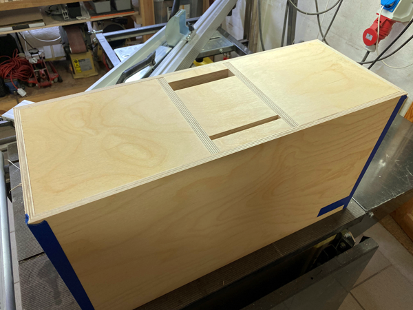
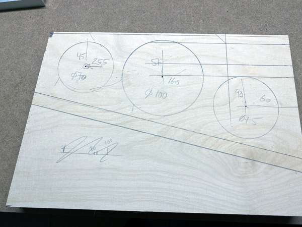
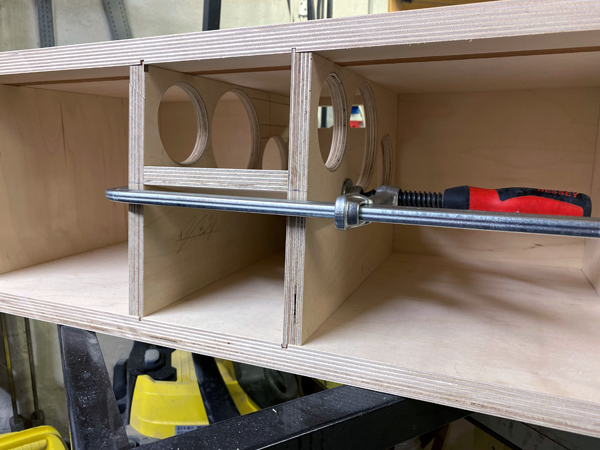
Rear panel showing the port and midrange slot. Coordinates for holes in
bracing/mid-cab measured from top and rear.Placement not critical.
I made the rear panel from several pieces as can be seen, makes it
easier to make the port and slot.
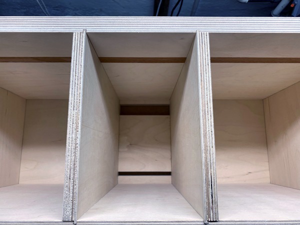
Glue the upper panel in midrange cabinet before cabinet assembly, so you
can slide in the structure.
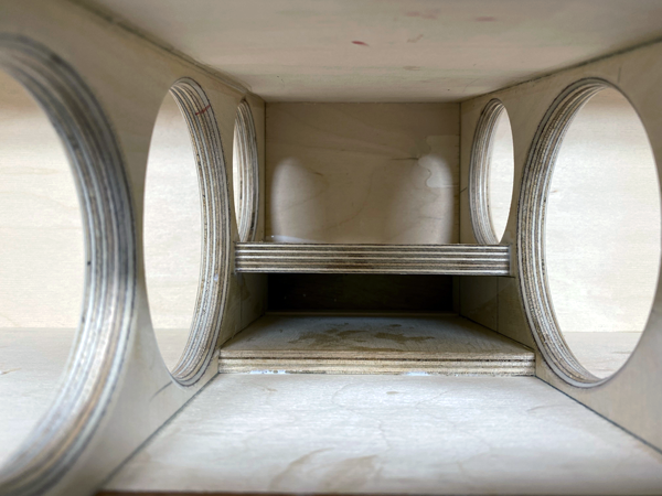
Port in place.
Sanded and ready for lacquer.
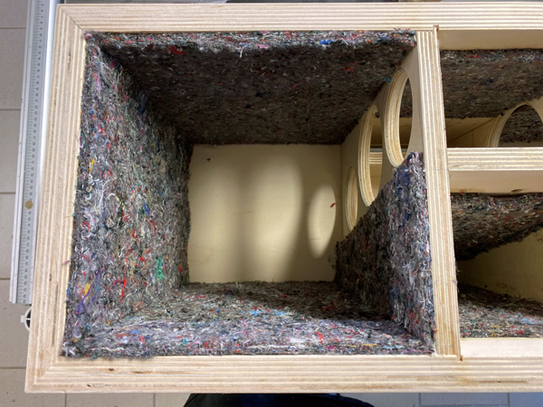
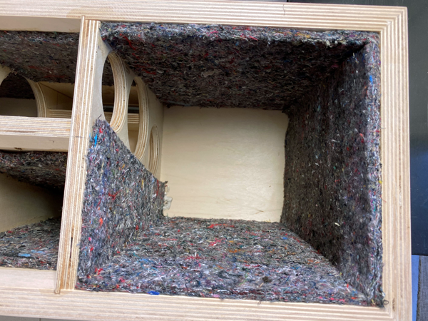
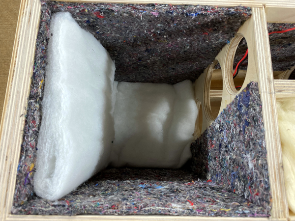
Damping of left and right compartment.
The rear panel free to carry crossovers and be cored by acoustilux.
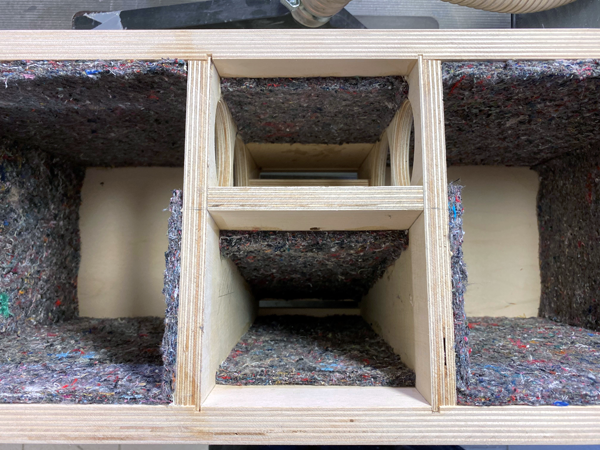
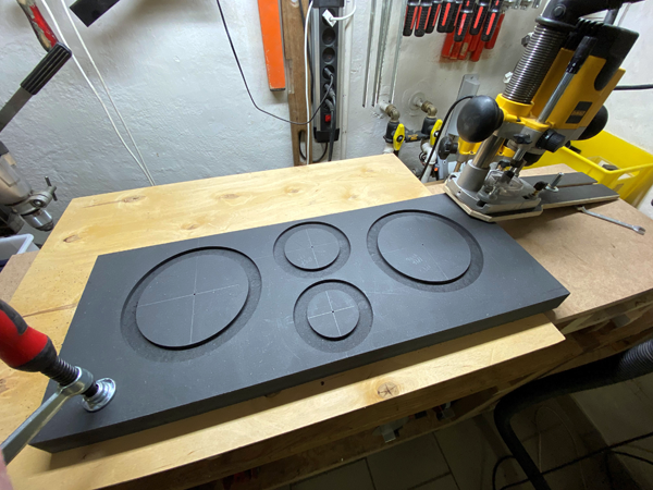
Mid and tweeter cab damping. Right: Start of routing for drivers.
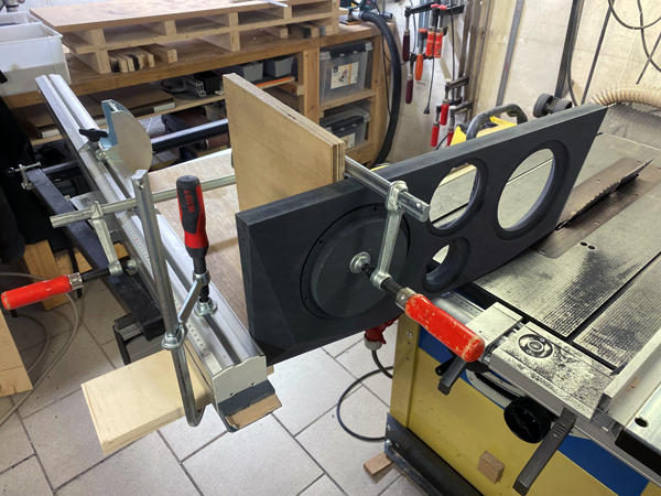
Faceting the front panel is optional. I think it looks great.
Doing it on a table saw is easy, but can be done by hand:
http://www.troelsgravesen.dk/tips.htm#Faceting
Sawblade angle set på 23 deg. Guide set to 6 deg. (for the vertical
faceting) and 7 deg for the horizontal faceting.
Length of vertical faceting: 250 mm. Length of horizontal faceting: 200
mm.
Both to a depth of 25 mm - if panel thickness allows.
I made front panels 35 mm, excessive, but looks nice. I suggest 19-22 mm like the rest of the cabinet. Remember to chamfer the midrange cabinet hole, read here: http://www.troelsgravesen.dk/chamfer.htm. Very important, in particular if you use more than 19 mm. Do like this:
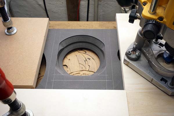
Picture taken from another construction. Mark the midrange cabinet
panels and chamfer to some 6-7 mm from the edge of the driver rebate.
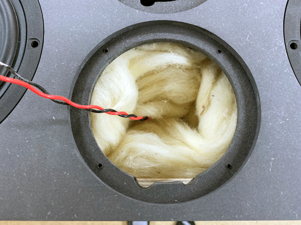
The midrange cabinet filled with sheeps wool, 75 grams.
Behind 18W drivers, add one folded sheet of acoustilux, 46 x 50 cm to
cover crossover and the side panel.
A few comments on
MEASUREMENTS before you start interpreting the readings below.
First of all, if we think measurements will
tell us how a speaker sounds, we're wrong. The perception of sound is
way too subjective to be reflected in any measurements we can perform. A
loudspeaker system is meant to give us a satisfying idea of an acoustic
event and for some people a pair of 5 USD ear-plugs are enough, others
spend 200 kUSD on a truly full-range pair of speakers - and the latter
may not be happier than the former.
Measurements may give us an idea of tonal balance of a system, i.e. too
much or too little energy in certain areas, although dispersion
characteristics play a vital role here. A two-way 7+1 and a three-way
7+4+1 may display similar horizontal dispersion, yet sound very
different. Measurements may tell us about bass extension if far-field
measurements are merged with near-field measurements. In addition to
this, ports may contribute to bass extension. Most of we diy'ers do not
have access to an anechoic room for full-range measurements from
20-20000 Hz.
What cannot be seen is what kind of bass performance we get in a given
room. Bass performance is highly dependent on in-room placement of your
speaker and the same speaker can be boomy in one place and lean in
another. Actual SPL level at 1 meter distance and 2.8V input is useful
for en estimate of system sensitivity and combined with the impedance
profile may give an idea of how powerful an amplifier is needed to drive
the speaker to adequate levels.
What measurements do not tell is the very sound of the speaker unless
displaying serious linear distortion. The level of transparency, the
ability to resolve micro-details, the "speed" of the bass, etc., cannot
be derived from these data. Distortion measurements rarely tell much
unless seriously bad, and most modern drivers display low distortion
within their specified operating range.
Many people put way too much into these graphs and my comments here are
only meant as warning against over-interpretation. There are more to
good sound than what can be extracted from a few graphs. Every graph
needs interpretation in terms of what it means sonically and how it
impacts our choice of mating drivers, cabinet and crossover design.
What measurements certainly do not tell is the sonic signature of the
speaker, because speaker cones made from polypropylene, aluminum,
Kevlar, paper, glass fiber, carbon fiber, magnesium, ceramics or even
diamonds all have their way of adding spices to the stew. Nor do
measurements tell what impact the quality of the crossover components
add to the sound, from state of the art components to the cheapest of
coils and caps, they all measure the same if values are correct, yet
sound very different.
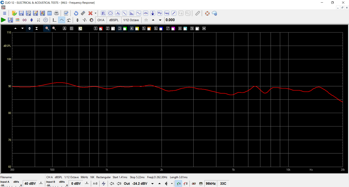
Frequency response measured at 0.5 meter, normalised for 1m/2.8V.
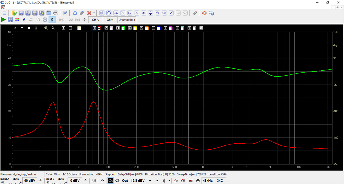
Final system impedance, quite an 8 Ohm speaker. Green = electrical
phase.
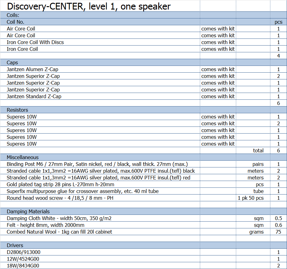
Above parts list, level 1
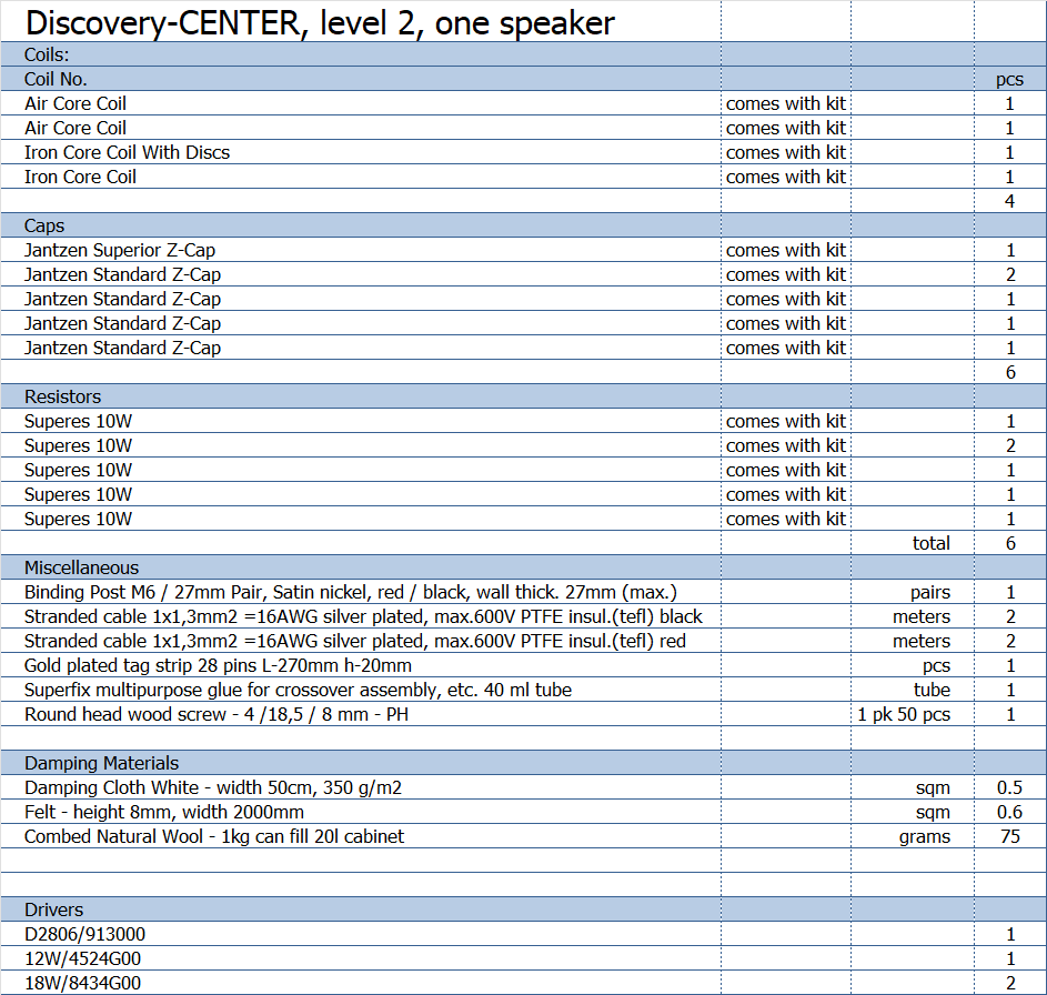
Above parts list level 2. Caps for midrange and bass, all STANDARD-Z
caps.
All kit and component prices may be subject to change and are always to be confirmed by Jantzen Audio Denmark.
Download Kit Sale Presentations:
![]()
All technical questions to troels.gravesen@hotmail.com
All questions regarding purchase of kits, please mail Jantzen Audio at contact@jantzen-audio.com
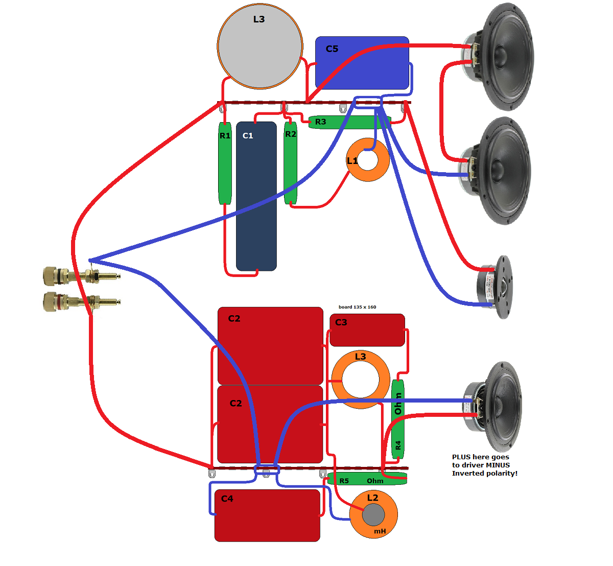
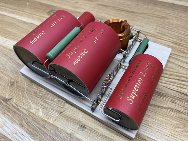
CROSSOVER-LAYOUT
BACK TO INDEX
Check this out before start making crossovers:
http://www.troelsgravesen.dk/tips.htm#CONSTRUCTION_OF_CROSSOVERS
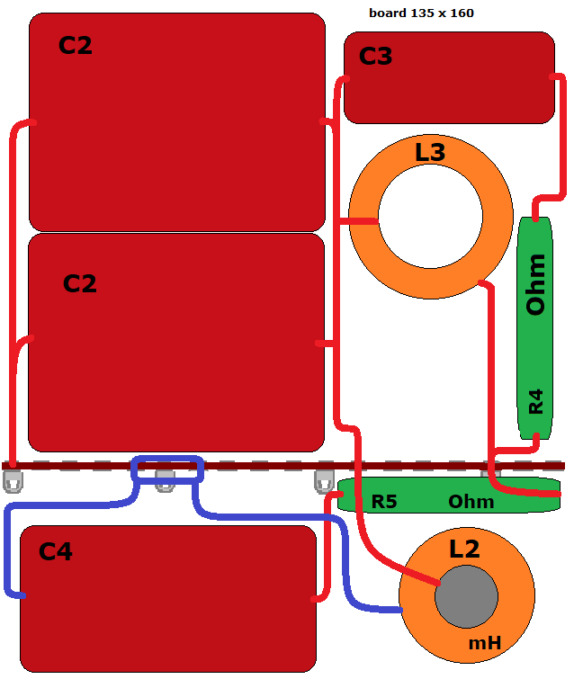
Above crossover layout for bass and tweeter.
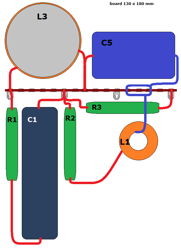
Above crossover layout for midrange.
For level 2, the caps will obviously be much smaller and the board
height can be reduced.
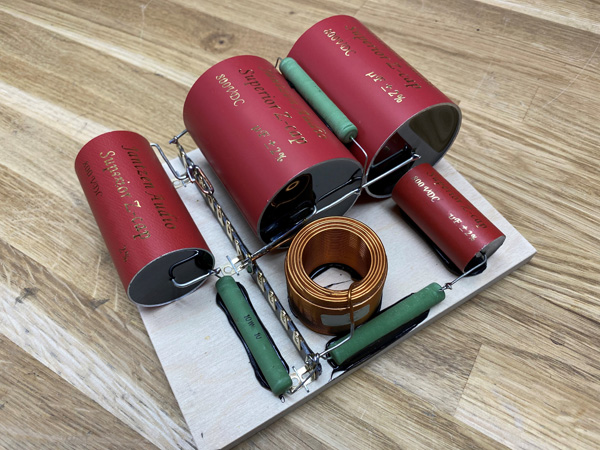
Above the midrange crossover.
Pay notice L2 is missing here. Follow the drawing.
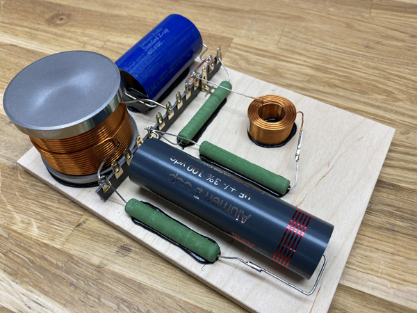
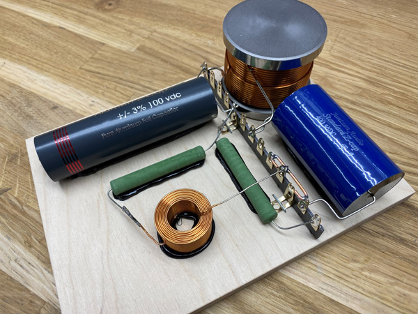
Above the crossover for bass and tweeter.
Crossovers placed in cabinet.
Speaker wiring: