Discovery 18 crossovers
Copyright 2013 © Troels Gravesen
On this page you'll be taken through four different crossovers (!). Yes, this is why I put it on a different page because it may be utterly boring to some readers and if crossovers are not your bedtime reading you can stick to the main page.
A few comments on
MEASUREMENTS before you start interpreting all the
readings below.
First of all, if you think measurements will tell you how a speaker
sounds, you're wrong, very much wrong indeed. The perception of sound is
way too subjective to be reflected in any measurements we can perform. A
loudspeaker system is meant to give us a satisfying idea of an acoustic
event and for some people a pair of 5 USD ear-plugs are enough, others
spend 200 kUSD on a truly full-range pair of speakers - and the latter
may not be happier than the former.
Measurements may give
us an idea of tonal balance of a system, i.e. too much or too little
energy in certain areas. Measurements may tell us about bass extension
if far-field measurements are merged with near-field measurements. In
addition to this, ports may contribute to bass extension. Most of us
diy'ers do not have access to an anechoic room for full-range
measurements from 20-20000 Hz.
What cannot be seen is what kind of bass performance we get in a given
room. Bass performance is highly dependent on in-room placement of your
speaker and the same speaker can be boomy in one place and lean in
another. Actual SPL level at 1 meter distance and 2.8V input is useful
for en estimate of system sensitivity and combined with the impedance
profile may give an idea of how powerful an amplifier is needed to drive
the speaker to adequate levels.
What measurements do not tell is the very sound of the speaker unless
displaying serious linear distortion. The level of transparency, the
ability to resolve micro-details, the "speed" of the bass, etc., cannot
be derived from these data. Distortion measurements rarely tell much
unless seriously bad, and most modern drivers display low distortion
within their specified operating range.
Many people put way too much into these graphs and my comments here are
only meant as warning against over-interpretation. There are more to
good sound than what can be extracted from a few graphs. Every graph
needs interpretation in terms of what it means sonically and how it
impacts our choice of mating drivers, cabinet and crossover design.
What measurements certainly do not tell is the sonic signature of the
drivers, because cones made from polyprop, alu, kevlar, paper, glass
fiber, carbon fiber, magnesium, ceramics or even diamonds all have their way of
colouring the sound.
CROSSOVER v1, flat front panel
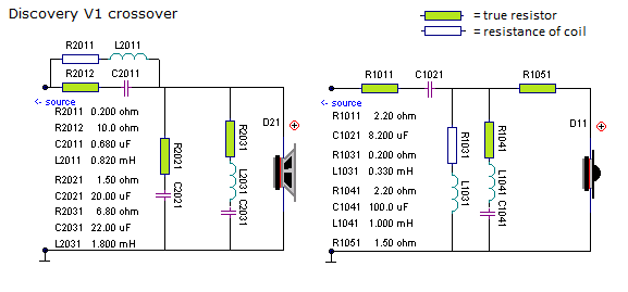
The V1 crossover is basically the same as the "Dali" crossover shown on
the Discovery
main plus page a couple of refinements. The midbass series coil is 0.82 mH
providing a decent flat response in the 300-600 Hz range but with the
result of too much energy in the upper mid. The LCR circuit 2031 dampens
the energy in this range. Furthermore an RC circuit across series coil
dampens the energy in the 4-5 kHz range providing a close to LR4
roll-off profile.
Tweeter circuit features an LCR circuit dampening the impedance peak and
shapes the roll-off towards a better LR2 profile.
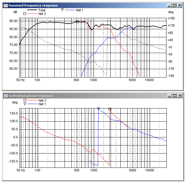
Thus, an asymmetrical crossover with a better balanced midrange and the
midbass not fiddling too much in treble range. Tweeter roll-off is
improved and provides increased power handling. Still, phase integration
is not better than the simple "Dali" solution. Point of crossover is
2400 Hz.
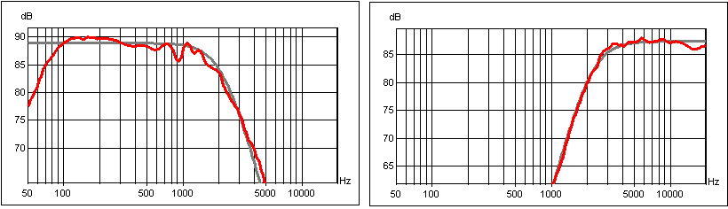
Above the basic response of the drivers
measured at 0.5 m distance. Bass response merged with nearfield response
@ 250 Hz.
Tweeter response is nice and flat between 2-22 kHz but has a minor bump
between 1 and 2 kHz. At first I wanted to change the front panel layout
to see if a more smooth tweeter roll-off could be achieved, but
simulation proved this bump not to be a major problem.
Left: The beginning of the bass crossover.
Red = response with no components. Green = 0.82 mH coil inserted. Blue =
R2021 and C2021 added. As can be seen this creates quite a bump at 1
kHz. All as expected. To smooth the 600-1500 Hz range a parallel notch
filter was added = yellow graph.
Right: The RC circuit across L2011 helps shaping the bass driver upper
roll-off and I was in doubt whether this was really needed. Only when
the crossover was finished did I try +/- this RC circuit and it stayed
in.
Now, in principle the crossover the should be
finished but listening tests suggested a little too much energy in the
800-1500 Hz range, thus the bass LCR circuit was modified and the result
can be seen above to the right. This makes a difference and takes away
some of the forward sound of the simulated crossover.
Left: Tweeter crossover was easy and only
thing left was the LCR circuit smoothing the impedance peak at 650 Hz.
This LCR circuit also helps smoothing the low-end roll-off and playing
at loud levels, it could be heard if it was there or not. As can be seen
from left hand graph, the summed response is not impacted by this LCR
circuit.
Right: Response of drivers driven from crossover (black and pale green),
summed response (red) and response with inverted (negative) tweeter
polarity. Now, this is basically a 2nd order LR filter and tweeter is
supposed to be inverted in such a set-up, but only if drivers are
time-aligned - and they are certainly not. The tweeter is some 25-30 mm
in front of the bass driver and due to the time difference, we end up
with connecting the drivers with the same polarity. Measurements done at
½ meter distance and at a height a little below center of the tweeter.
This is very much how these things go when we do nothing to to
time-align the drivers and this is also the case for the Dali 310
crossover.
Above to the left horizontal dispersion at 0,
10, 20, 30 and 40 deg. Quite an even power response.
Vertical dispersion doesn't look quite as good but to be honest, better
than many other speakers. The measurements were done a ½ m distance from
a height of bass center and up to upper edge of cabinet. I didn't
measure the actual angles but this gives you san idea of vertical
dispersion. This is not a speaker that should be tilted backwards.
Optimal listening height is at tweeter level.
Left:Above step response displaying positive
polarity of both drivers, but with tweeter quite in front of bass
drivers.
Right: Mounting the R2604 tweeter and reducing R1011 to 1R0 produce the
red graph. Blue graph is crossover V2 with D2604.
The same crossovers can be used for both speakers by adjusting the
series resistor R1011.
CROSSOVER v2, flat front panel
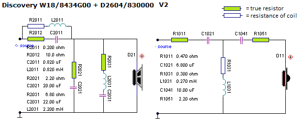
Crossover for D2604 version.
For R2604, use 0 ohm (short) for R1011.
The V2 crossover features the same midbass section as V1 but this time we use the common DIY solution of a 3rd order filter to the tweeter because now we can make a nice phase integration as can be seen from simulation below. The result is an LR4 topology to both drivers. Bass upper roll-off could be a little steeper, but this will do. Still midbass driver is some 25-30 mm behind tweeter and optimal listening height is at tweeter level. With the steep tweeter roll-off we no longer need taking care of tweeter impedance peak and the tweeter is well protected from any midrange influence. Price to pay is two caps for the tweeter section and they need to be really good.
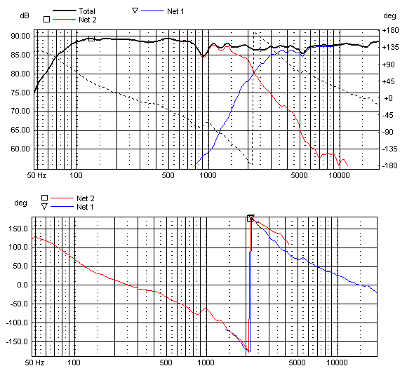
Above the simulation of the 2nd/3rd order crossover. As can be seen we have a smooth response and nice phase integration. Same polarity of both drivers due to the target transfer function in fact is an LR4 topology. Despite the lack of acoustic alignment we can manage both amplitude and phase, but as can be seen from step response below we have the tweeter well in front of the midbass.
V2 measurements
Left: Disregard red graph (R2604). Blue is V2
crossover improving linearity. From right graph we can see a point of
crossover around 2300 Hz (purple dip).
Left: V2 from left and right speaker and R1011 = 2R2. Right: Impedance
of V2 system. Minimum 4 ohm at 500 Hz.
Step response from V2 crossover.
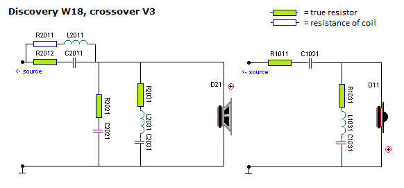
CROSSOVER v3, stepped front panel
R1011 for R2604 = 1.5 ohm
default (parallel 2R7 and 3R3 following the kit). Tune to personal
taste.
R1011 for D2604 = 2.7 ohm.
Tune to personal taste.
Component values comes with the kit from Jantzen Audio, so please do not
ask.
The V3 crossover is an LR2 filter with the midbass 22 mm in front of the tweeter panel. In reality the W18 may be some 25-27 mm behind the tweeter on a flat panel, but with a target LR2 filter we need to invert tweeter polarity and we also want the positive tweeter response to coincide with the rise of the W18 response. See colored step response below. This has been discussed on these pages and i detail on Joe Rasmussen's site here (close to bottom of page). The long and the short of it is that the tweeter goes positive at the same time as the midbass does. In fact this graph suggest I can make the front panel a little thinner than the 22 mm MDF I used for the test front panels. Simulation shows some +/- 3 mm really doesn't impact amplitude noticeable and it would be nicer with a thinner outer W18 front panel. For my final panels for this V3 crossover I'll use an 18 mm Baltic birch panel.
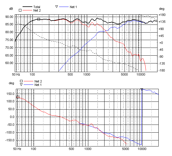
Crossover simulation from measurements done on stepped baffle where the W18 driver is mounted on a 22 mm MDF panel. Image on intro page. Below the target LR2 filter slopes and predicted response. Don't worry these wobble a little, reality looks better than these graphs as can be seen from measurements below.
Upper left: Response from drivers driven from V3
crossover and summed response (red). Upper right: The red and green
graphs show the impact of the upper mid LCR circuit (R2031/L2031/C2031).
This may seen very little but it does reduce and tendency to a too
forward upper mid and just increasing L2011 leaves a dip in the middle
midrange, thus the LCR circuit is to stay. The W18 response bump at 8-10
kHz is insignificant and removing it by another notch filter didn't
prove worthwhile.
Upper right: Inverting tweeter polarity leave a huge suck-out in the 1-5
kHz range suggesting good phase integration of the two drivers over a
wide range.
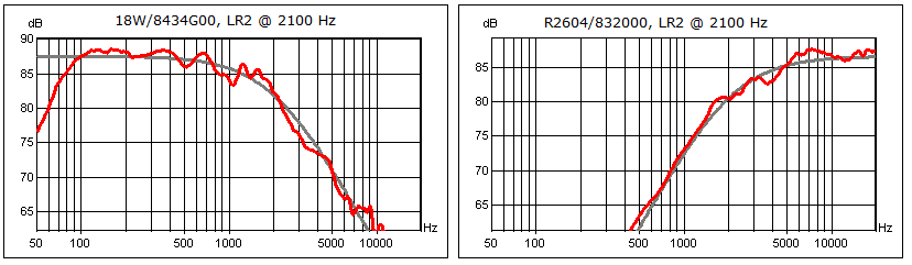
Upper left: The clean frequency response of V3
crossover, merged at 250 Hz with woofer near-field response. System
sensitivity = 87-88 dB/2.8V.
Upper right: This just to show the tweeter roll-off from the rather
unusual crossover consisting of only a single capacitor and an LCR
circuit not only smoothing impedance peak, but also shaping the tweeter
roll-off by the small value coil. This was the simplest way
the target LR2 slope could be achieved. No simple RL circuit could
produce the same result.
Upper left: Step response from V3 crossover showing tweeter connected with inverted polarity. Upper right: Individual step response of tweeter and midbass. See discussion above.
Impedance of final system.
CROSSOVER v4, stepped front panel
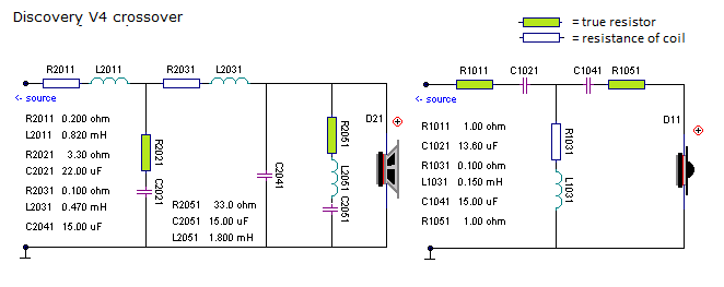
Crossover for R2604 version.
For D2604, use 2.2 ohm for R1011.
LR4 filters are always a pleasure in simulation. We have so many components available we can do almost anything. The simulation below is not from the schematics above as LCR2051 and C1021 and L1031 had to be tweaked in reality to produce a flat response.
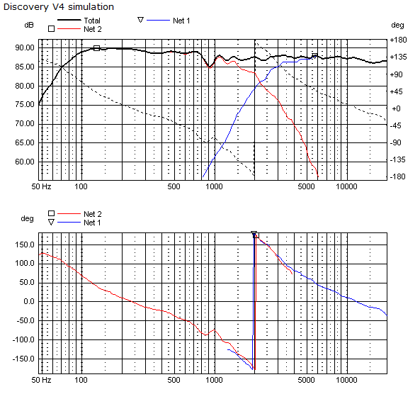
V4 simulation
The LR4 simulation target transfer functions.
MEASUREMENTS
Left: SPL normalised for 1m/2.8V. System
sensitivity = 87 dB/2.8V.
Right: Response of drivers driven from crossover (green and blue). Black
= summed response.
Left: Horizontal dispersion with D2604
tweeter @ 0, 10, 20 and 30 deg.
Right: Horizontal dispersion of R2604 tweeter @ 0, 10, 20 and 30 deg.
This is presumably why some people disfavour the ring-radiator Generally
standard domes have better dispersion in top octave (10-20 kHz).
Left: Light green = inverted tweeter
polarity. We can also see point of crossover is 2200 Hz.
Right: Tweeter attenuation for D2604 is a bit more tricky than for the
R2604:
High level: R1011 = 1.0 ohm, R1051 = 2.2 ohm.
Middle level: R1011 = 1.0 ohm, R1051 = 2.7 ohm.
Low level: R1011 = 1R5 and R1051 = 2.7 ohm.
The transfer function of this 4th order crossover is quite dependent of
these two resistors, so not too much fiddling here.
Left: Step response of final system.
Right: Step response of individual drivers. As can be seen, this is in
no way fully time-aligned despite a 22 mm extra midbass baffle.
Final system impedance of LR4 crossover.
Minimum 2.5 ohm @ 3 kHz. Don't worry, no transistor amp will mind.