ScanSpeak
Illuminator-CENTER
Copyright 2022 © Troels Gravesen
Go to on this page:
DRIVERS
CROSSOVER
CABINET
WORKSHOP PICS
MEASUREMENTS
SPEAKER-KIT
CROSSOVER LAYOUT
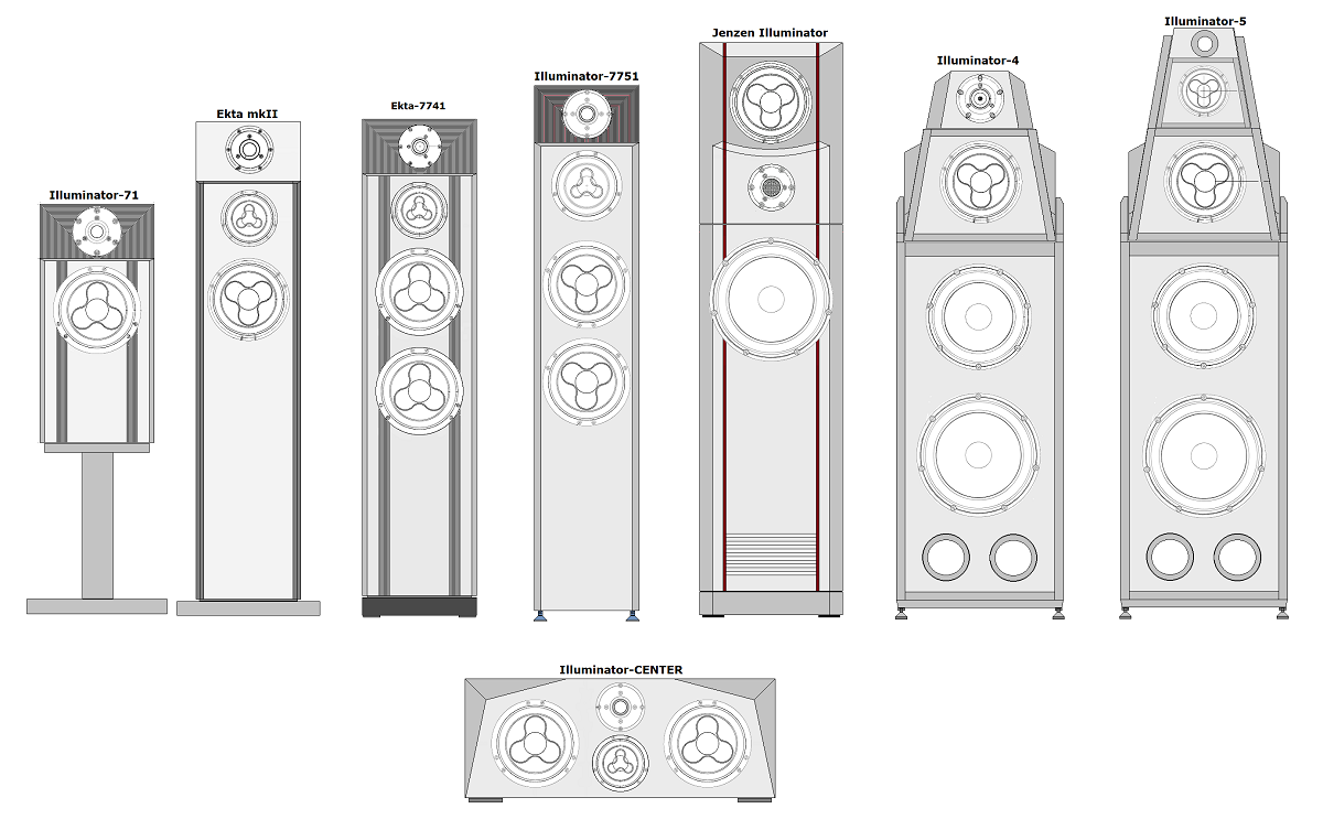
After making illustrations of the various
ScanSpeak family of speakers, I
couldn't help seeing something missing in the Illuminator range of
speakers. A center speaker based on Illuminator drivers. I wanted it to
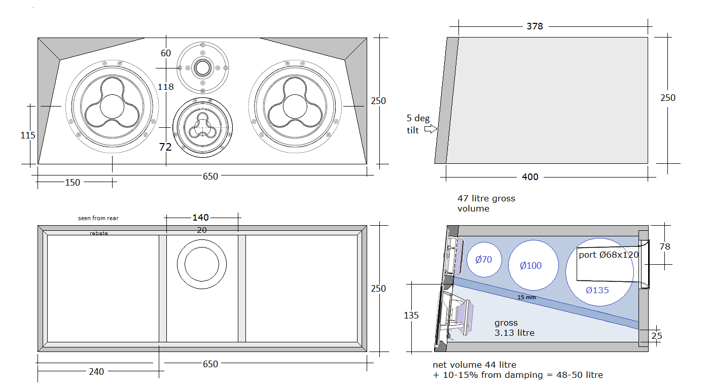
look like the drawing below.
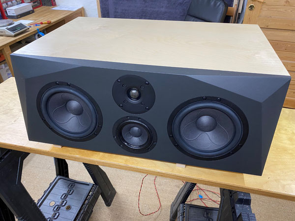
Thus, here an Illuminator-CENTER construction to make the picture
complete.
Center speakers for surround sound hasn't had high priority, as we just
simply do not sell a lot of them. Very few in fact. On the other hand,
making a single cabinet isn't that much work, so here it is.
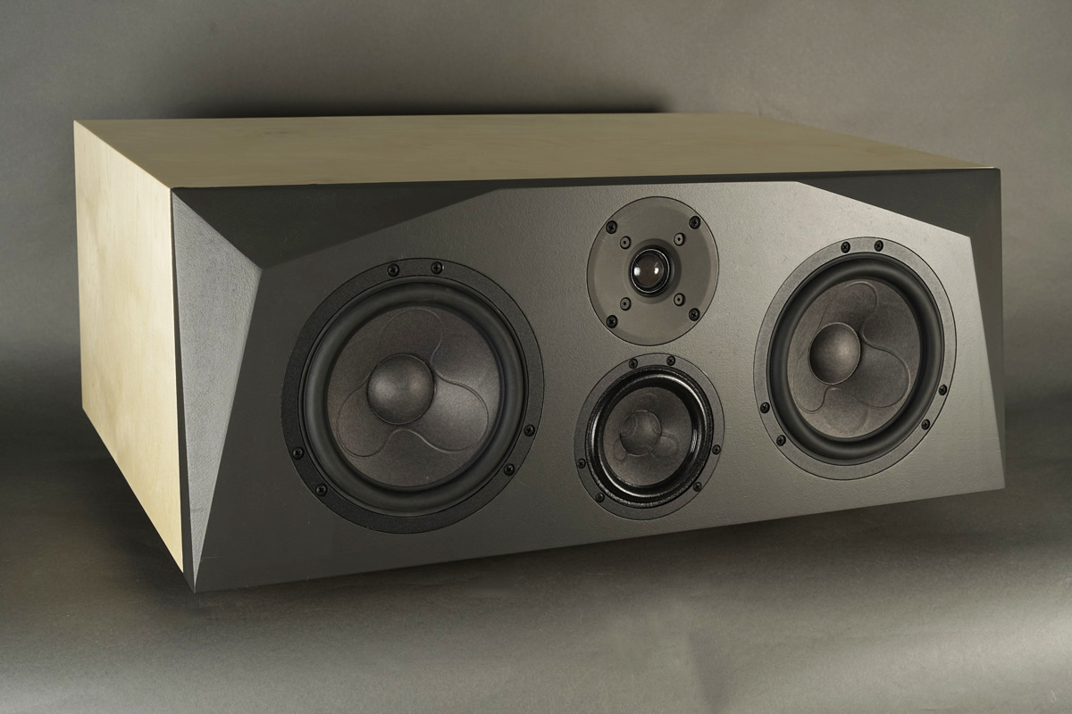
And it turned out to be quite a powerful speaker, that would also be
suitable for monitoring when making two.
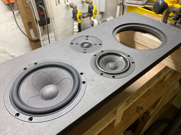
The Illuminator-CENTER obviously had to have the phenomenal 12MU as midrange driver - and here driven from a fairly low point of crossover ensures excellent dispersion in the midrange and so important for speech in a surround set-up. Like the Ekta-mkII and Illuminator-7751, I chose to use the D2608/913000 tweeter again. If it works, don't change it.
Basics:
4-driver speaker.
Dimensions: 65 x 40 x 25 cm, WxDxH.
System sensitivity: 90 dB/2.8V/1 meter.
Impedance: 4-8 Ohms.
Power requirement: 20+ watts/channel.
Power handling: 200 watts.
Please
also read:
http://www.troelsgravesen.dk/power-handling.htm,
and remember any burned driver is a misused driver.
Useful links (Please read before writing!):
http://www.troelsgravesen.dk/tips.htm
http://www.troelsgravesen.dk/crossovers.htm
http://www.troelsgravesen.dk/LCR-RC.htm
http://www.troelsgravesen.dk/Inverted-Polarity.htm
http://www.troelsgravesen.dk/choices.htm
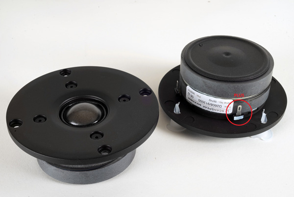
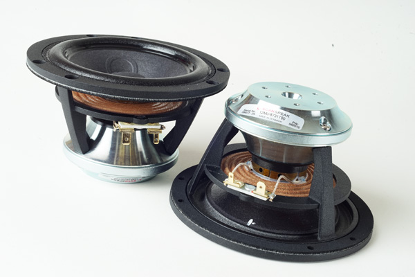
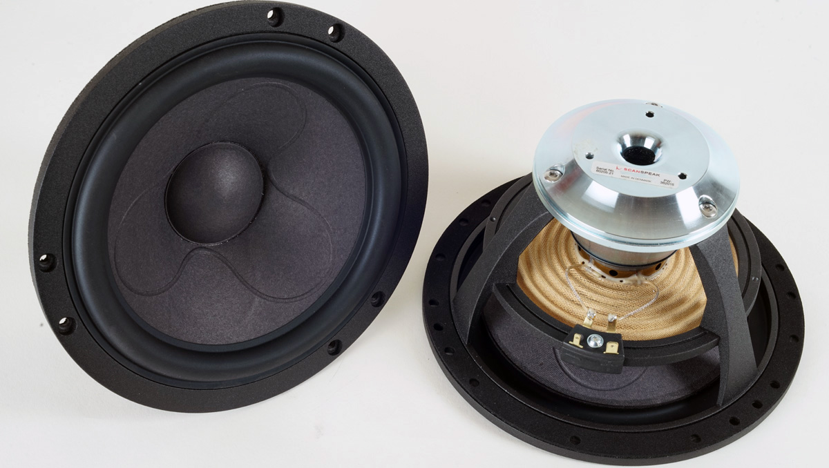
Download specs here: D2608/913000 12MU/8731T00 18WU/8741T00
Click image to view large.
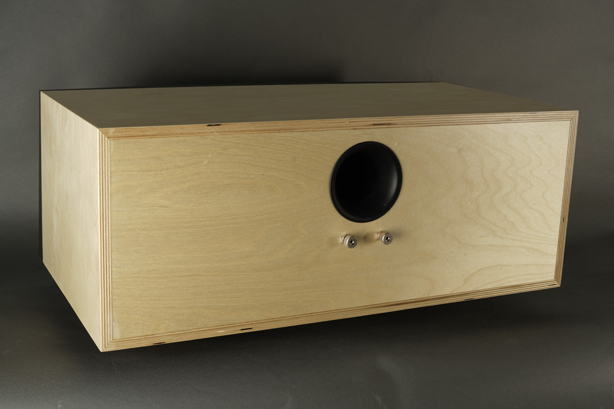
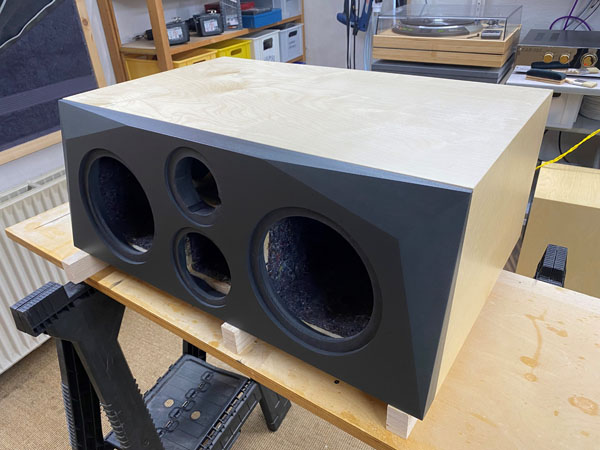
Cabinet was made from 20 mm Baltic birch and 15 mm for the internal
panels. Chamfering of the front panel is optional, but looks nice.
You can make the front panel vertical if placed high. Use 390 mm depth +
front panel.
Flat-pack cabinets now available from EBEL Holztecnik, Germany:
https://www.ebelholztechnik.de/galerien/index.php/category/419-illuminator_center
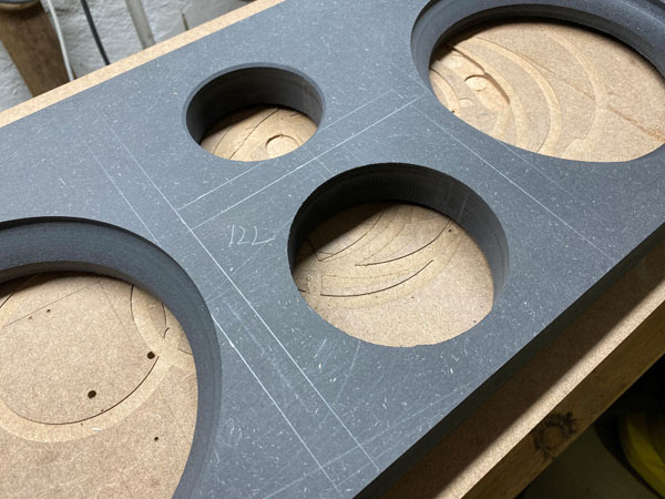
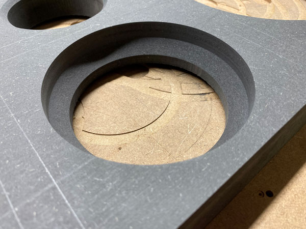
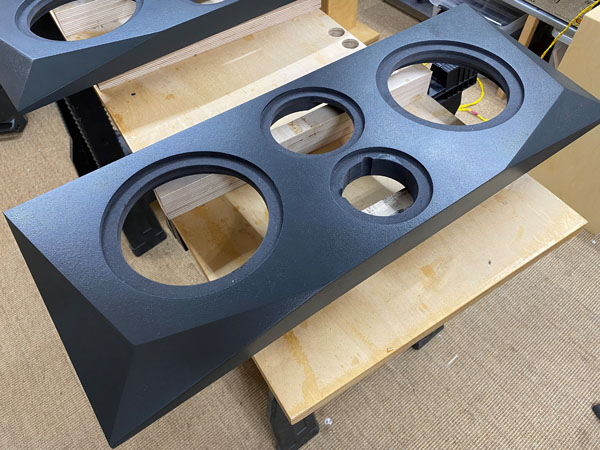
Making the front panels. As can be seen from
a 35 mm front panel, the driver hole chamfering becomes important, not
least for the midrange.
Start chamfering 45 deg. down to around 8-10 mm from the rebate edge.
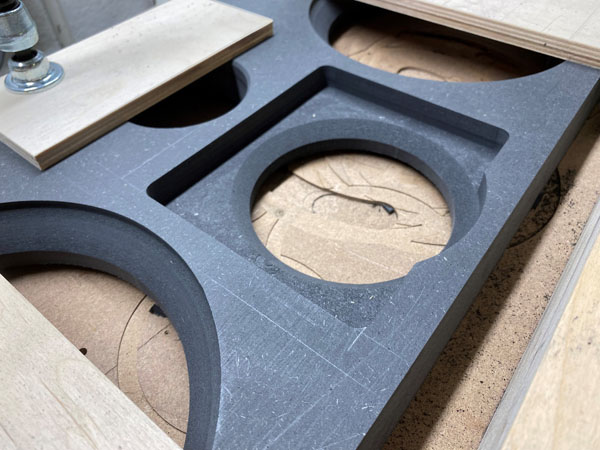
Set up boundaries for your router and route
down some 15-17 mm. This provides sufficient breathing for the midrange.
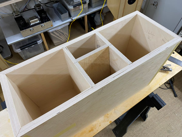
Some pics from the making of cabinets.
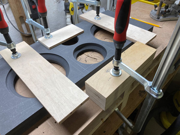
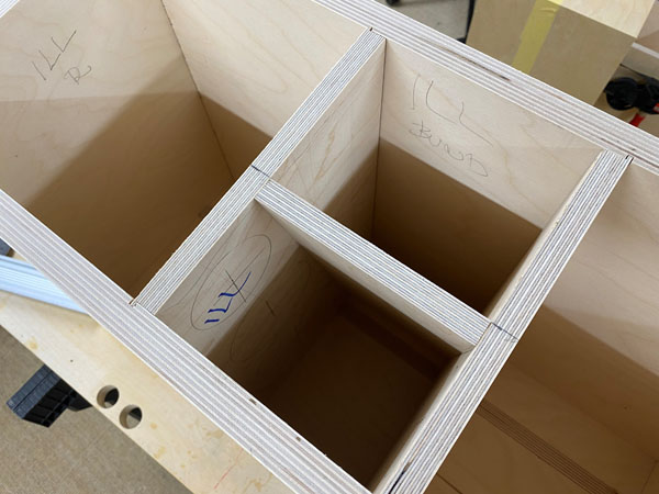
Time to route holes in the vertical panels above the midrange cavity.
The midrange upper panel was cut 9 deg. front and 14 deg. rear to fit
front panel and rear panel.
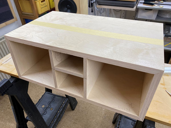
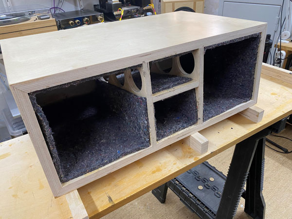
Cover all panels with felt except rear panel
behind midbass drivers. This is where the crossovers will be.
Front panel was added three coats of water
based paint before glued to cabinets.
Speaker now ready for measurements and crossover design.
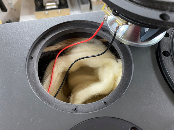
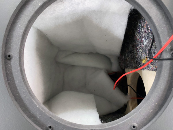
Add ~80 grams of wool to the midrange cabinet.
Fold a piece of 40 x 50 cm acoustilux and place behind each 18WU driver
like seen on photo.
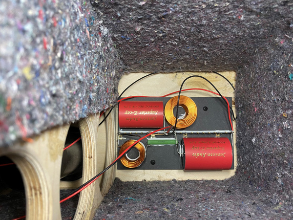
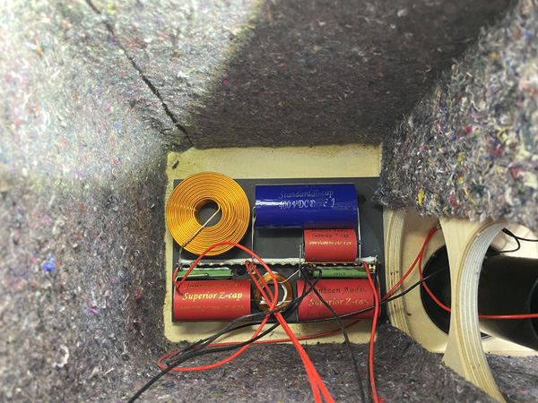
Crossovers placed on rear panel behind
mid-bass drivers.
A few comments on
MEASUREMENTS before you start interpreting the readings below.
First of all, if we think measurements will
tell us how a speaker sounds, we're wrong. The perception of sound is
way too subjective to be reflected in any measurements we can perform. A
loudspeaker system is meant to give us a satisfying idea of an acoustic
event and for some people a pair of 5 USD ear-plugs are enough, others
spend 200 kUSD on a truly full-range pair of speakers - and the latter
may not be happier than the former.
Measurements may give us an idea of tonal balance of a system, i.e. too
much or too little energy in certain areas, although dispersion
characteristics play a vital role here. A two-way 7+1 and a three-way
7+4+1 may display similar horizontal dispersion, yet sound very
different. Measurements may tell us about bass extension if far-field
measurements are merged with near-field measurements. In addition to
this, ports may contribute to bass extension. Most of we diy'ers do not
have access to an anechoic room for full-range measurements from
20-20000 Hz.
What cannot be seen is what kind of bass performance we get in a given
room. Bass performance is highly dependent on in-room placement of your
speaker and the same speaker can be boomy in one place and lean in
another. Actual SPL level at 1 meter distance and 2.8V input is useful
for en estimate of system sensitivity and combined with the impedance
profile may give an idea of how powerful an amplifier is needed to drive
the speaker to adequate levels.
What measurements do not tell is the very sound of the speaker unless
displaying serious linear distortion. The level of transparency, the
ability to resolve micro-details, the "speed" of the bass, etc., cannot
be derived from these data. Distortion measurements rarely tell much
unless seriously bad, and most modern drivers display low distortion
within their specified operating range.
Many people put way too much into these graphs and my comments here are
only meant as warning against over-interpretation. There are more to
good sound than what can be extracted from a few graphs. Every graph
needs interpretation in terms of what it means sonically and how it
impacts our choice of mating drivers, cabinet and crossover design.
What measurements certainly do not tell is the sonic signature of the
speaker, because speaker cones made from polypropylene, aluminum,
Kevlar, paper, glass fiber, carbon fiber, magnesium, ceramics or even
diamonds all have their way of adding spices to the stew. Nor do
measurements tell what impact the quality of the crossover components
add to the sound, from state of the art components to the cheapest of
coils and caps, they all measure the same if values are correct, yet
sound very different.
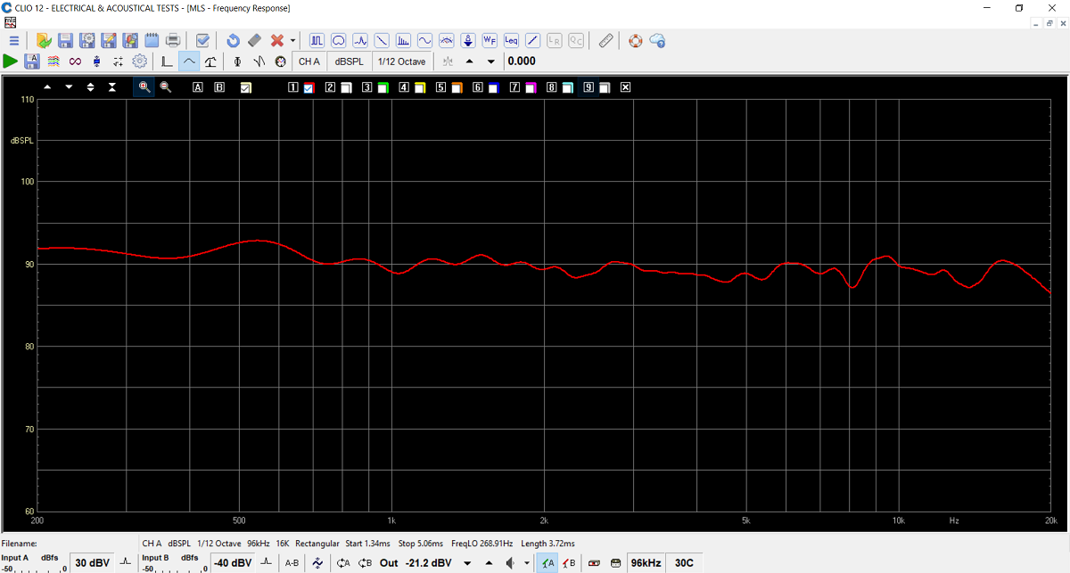
Frequency response of final system.
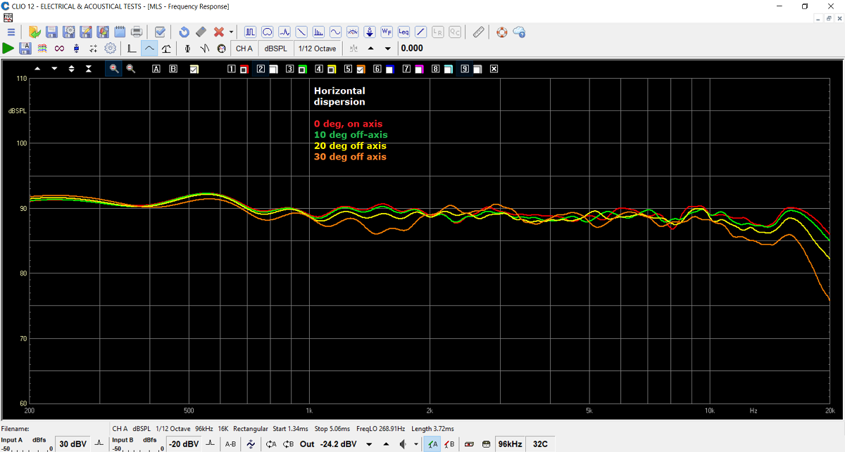
Horizontal dispersion @ 0, 10, 20 and 30 deg. off-axis.
This ensures a wide homogeneous listening window.
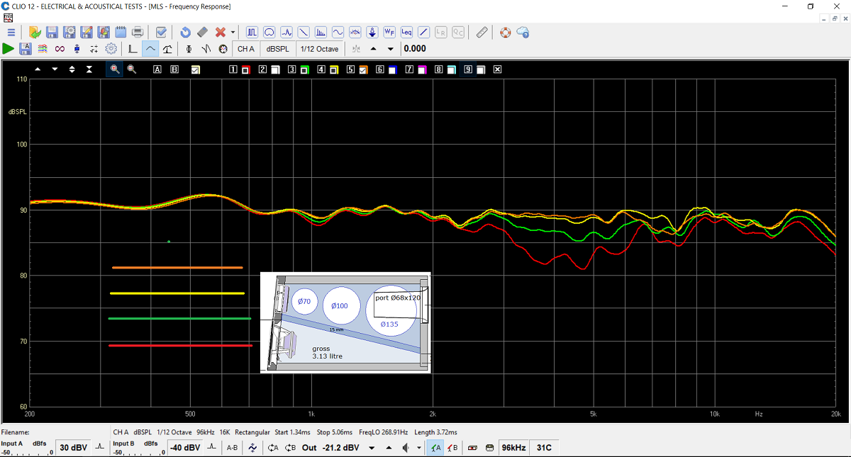
Vertical dispersion and heights shown in colours.
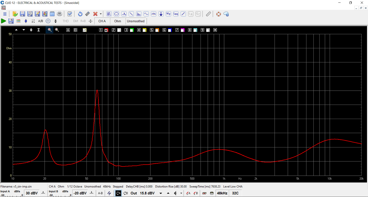
Final system impedance.
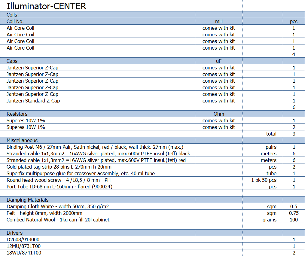
All kit and component prices may be subject to change and are always to be confirmed by Jantzen Audio Denmark.
Kits can always be bought with/without drivers, or some of the drivers.
Download Complete Kit Sale Presentations:
![]()
All technical questions to troels.gravesen@hotmail.com
All questions regarding purchase of kits, please mail Jantzen Audio at contact@jantzen-audio.com
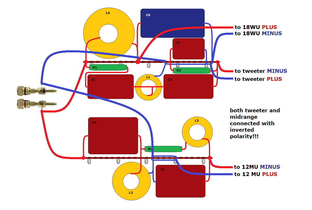
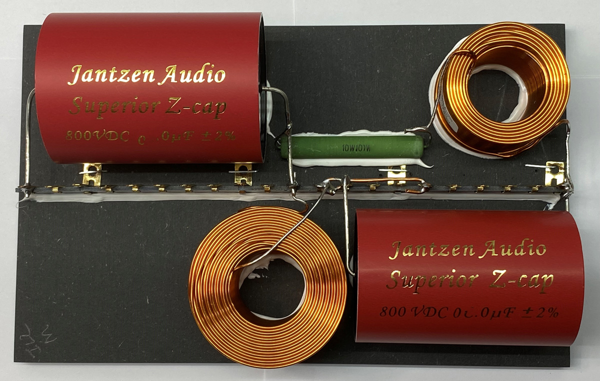
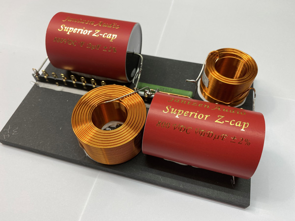
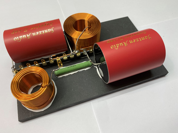
CROSSOVER-LAYOUT
BACK TO INDEX
Check this out before start making crossovers:
http://www.troelsgravesen.dk/tips.htm#CONSTRUCTION_OF_CROSSOVERS
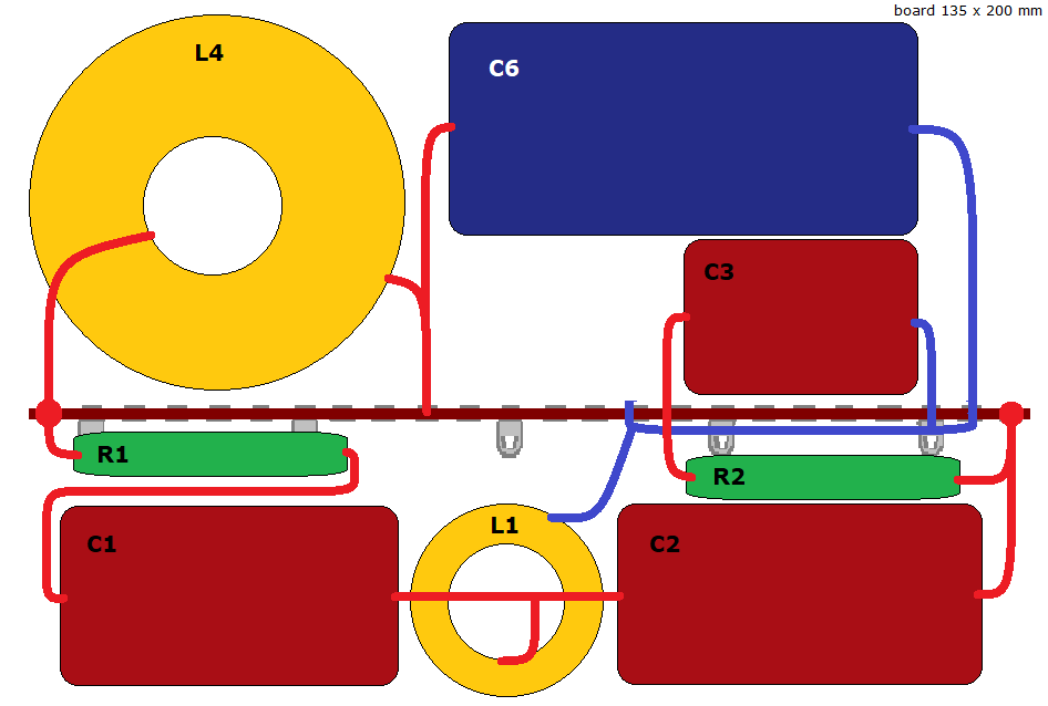
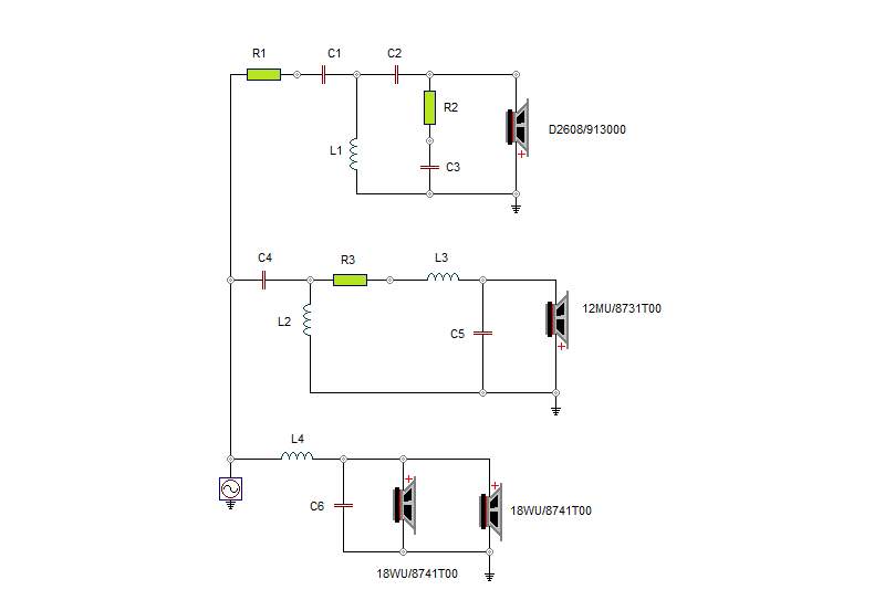
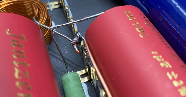
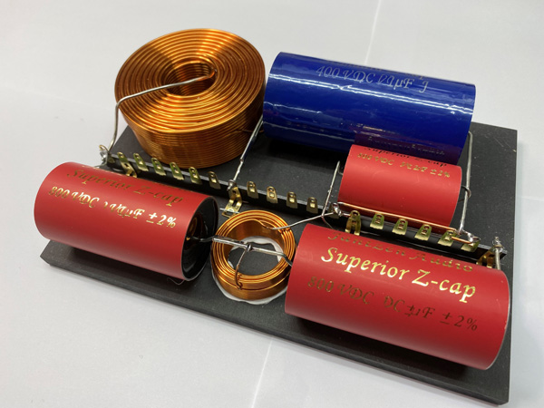
Crossover layout for bass and tweeter.
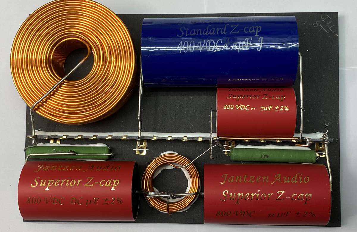
Bass-tweeter crossover.
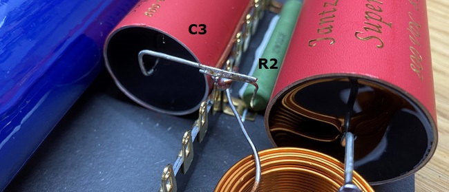
Pay notice R2 connects to C3 over the solder tag strip.
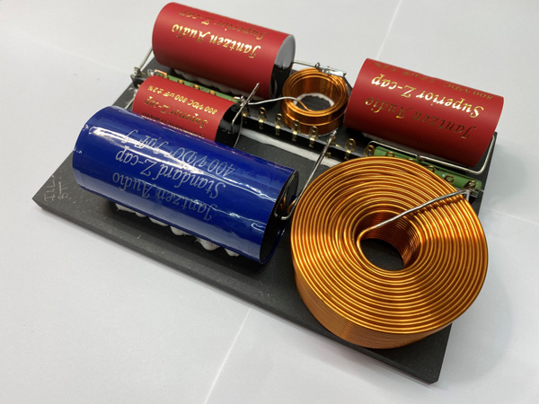
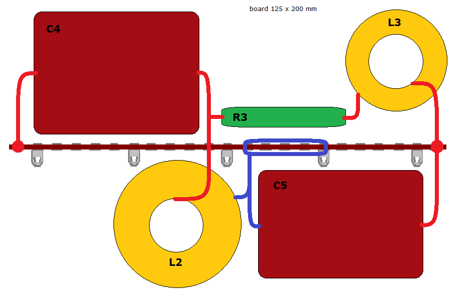
Crossover layout for midrange.
Midrange crossover.
Speaker wiring:
Pay notice to tweeter and midrange connected with inverted polarity!!