DIY Loudspeakers: HOME INDEX UPDATES RESPONSE WHAT'S NEW
JBL L112 Century II Up-Grade Kit
Copyright 2016 © Troels Gravesen
Go to on this page:
DRIVERS
CROSSOVER
CABINET
MEASUREMENTS
SPEAKER-KIT
CROSSOVER LAYOUT
The JBL L112 was introduced around 1981 after several iterations of the
original L100 Century. What is to be found in the L112 is a crossover -
I mean a real crossover, not just some mid and tweeter protections like
the L100 (two caps). Getting into the crossover topology reveal some
surprising features as the bass and tweeter have a huge overlap and the
midrange driver acts as a filler between the two, but more on this
later.
Setting up the as-is speakers with mid attenuation at minus 3-5 dB and
tweeter attenuation to minus 2 (my client's preferred setting) revealed
a balanced performance with no apparent accentuation or depression of
any particular frequency band. Measuring the frequency response with
these settings also displayed a pretty linear response, maybe with a
little depression in upper-mid/lower treble, but this may sometimes be
needed if we have a wide dispersion in this area - and the LE5-12 middriver has good dispersion.
Due to the off-set of mid and tweeter, these speakers require careful
toing in to create the most stable sound image. Certainly a hot spot!
JBL could have made a better speaker from placing mid and tweeter on a
vertical line and if you're into woodworking, I suggest making new front
panels to do so.
Listening to the original crossovers was pleasant! As said, a balanced presentation and playing a wide range of genres, from rock, jazz to classical, didn't point to any serious problems like the peaky nature of the L100 midrange (LE5-2). Vocals were surprisingly good. Image stability wasn't too good and toing in the speakers only helped a little. What later could be seen from measurements was that the 1-7 kHz range is pretty much some mish-mash of response coming from all drivers. Placing the mid and tweeter on a vertical line would have helped, but with the new crossover this problem is far less pronounced, probably due to much less crossover lobing.
Getting the new crossover in action all of a sudden significantly improved the overall sound stage. Layers in the music, that before were somewhat smeared and congested, were now put into perspective due to much improved resolution. I made sure the overall voicing was pretty much the same as before, because I liked the voicing, but now bass transients came though with more punch, midrange with more clarity and cymbals appeared to float in the air and not just smeared treble spewed at you. The LE5 midrange drivers in all its iterations are kind of special. They don't go very low, they don't go particularly high, but they - for some reason - can be crossed higher than usual without beaming. The LE5 carries a lot of the treble energy and maybe because it does so well up to 5 kHz, may count for the coherent treble performance. 5 kHz is - by the way - not an unusual point of crossover for an upper-mid/lower-treble horn like the LE85. Maybe this was what the JBL engineers had in mind when they decided to make a small direct radiator. The LE5-12 is an easier mid-driver compared to the LE5-2 and doesn't display the serious peak at 7 kHz. The two LE5-12 drivers here were not from the same batch, but had a response +/- 1 dB from 700-6000 Hz. Not too bad for 35 year old drivers (see measurements below). The tweeters were more problematic, but with a point of crossover at 5 kHz, it's not too bad. Despite the ragged response from these tweeter, they performed much better than they should based on measured performance. This annoys me a bit, but I have to give in.
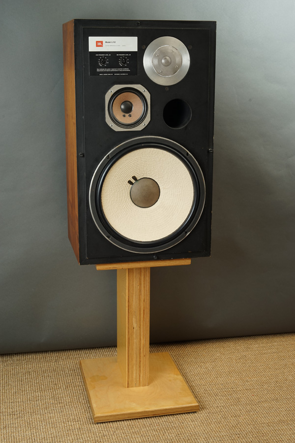
I tried different ways of placing the speakers and having almost all of the midrange from the 12" bass driver might call for placing the speakers on a stand with the bass on top. However, most people probably don't want to do this, hence my best recommendation is a 40 cm stand with the speakers tilted 5 deg. This works well in my living room.
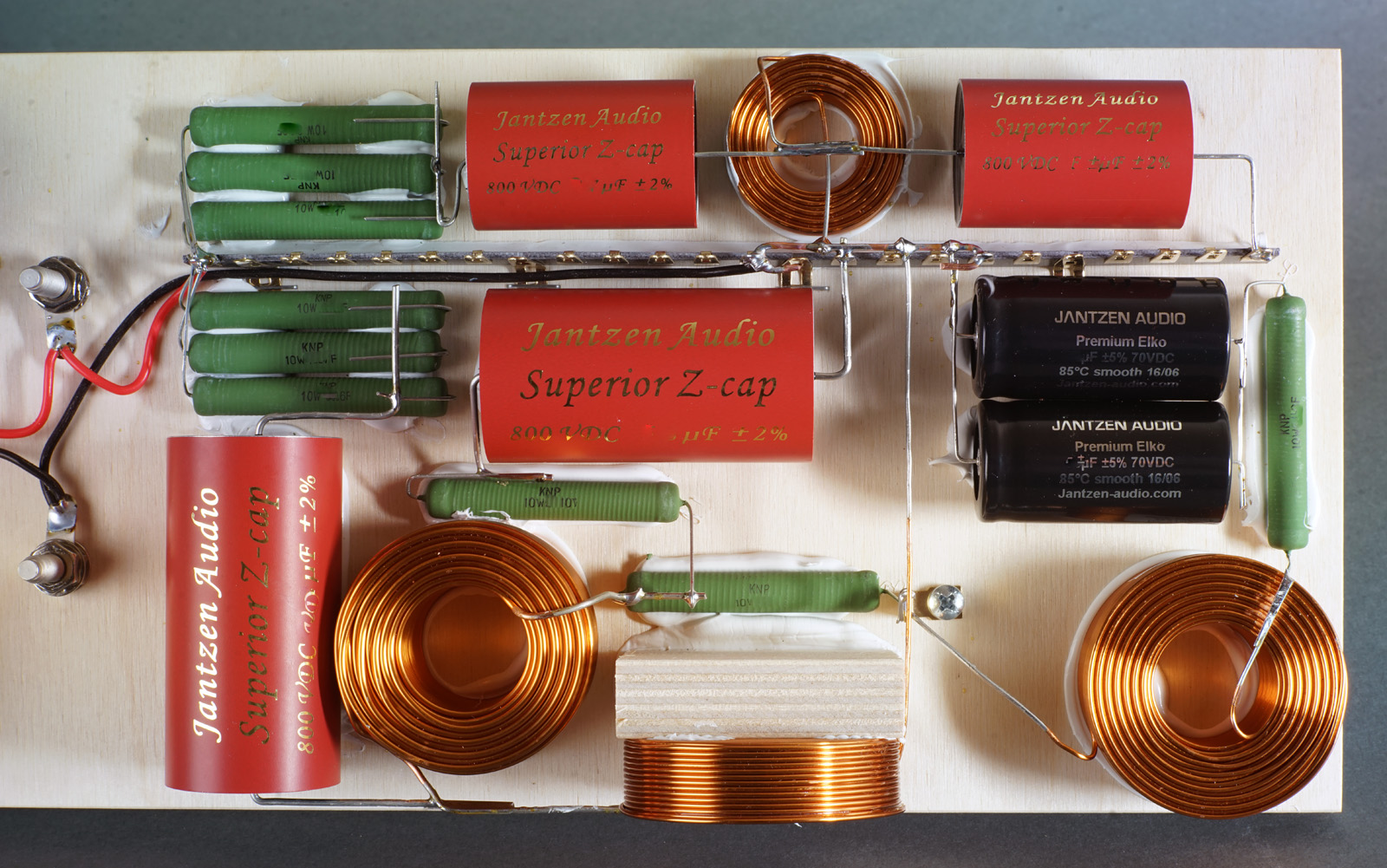
The Up-Grade Kit comes in three levels. The capacitors to the midrange and tweeter are the most important components, and we really do not get the full potential from using standard PP caps here (level 1). Not a whole lot of micro-farads goes into the circuit, hence level 2, which is shown here, use all Sup-Z caps for mid and tweeter except for one smooth-foil electrolytic (high-value) for taming the LE5-12 peak at point of resonance. Level 1 will use Alumen-Z for tweeter and midrange series capacitors and WAX coil for L3 and you get an even smoother response. Should you pick level 3, you might at a later stage replace C3 with a Superior-Z cap. This is the most important capacitor in the circuit. Next comes C1 and C9.
Please notice: The kit will not work for any other drivers than those listed here.
Download JBL L112 brochure
here.
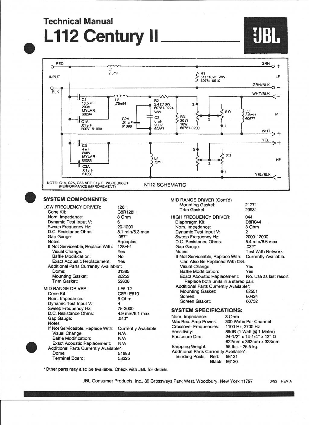
Download Technical Manual
here.
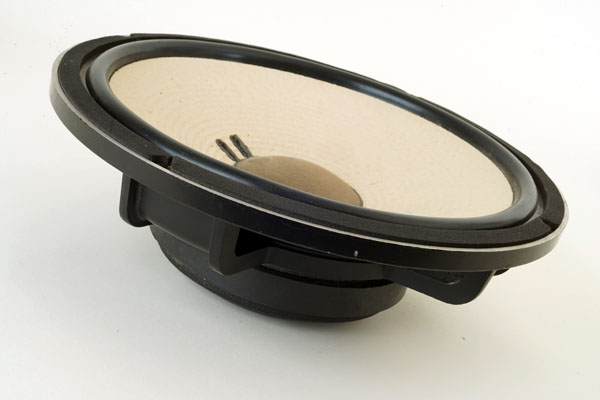
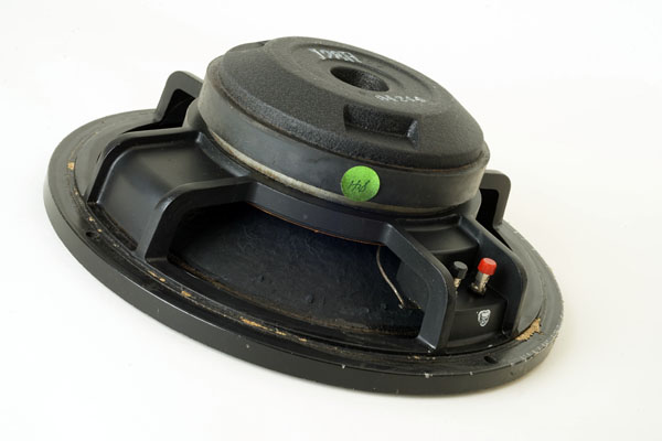
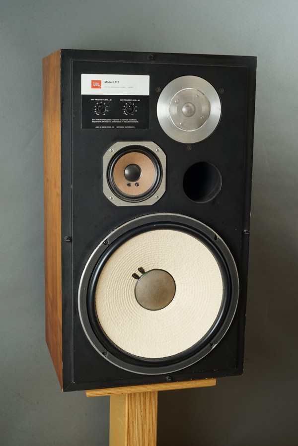
JBL L-112 bass driver:
128H
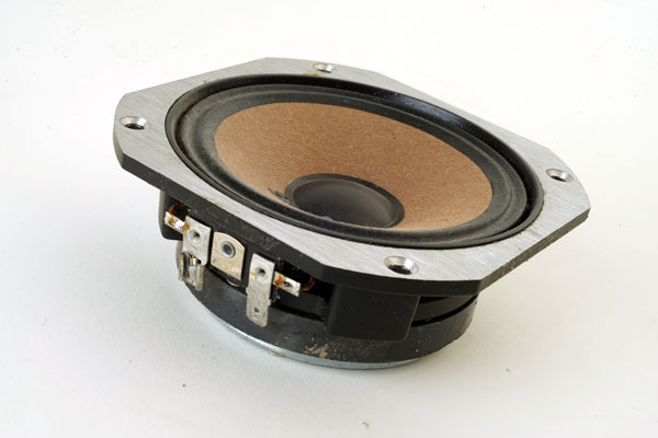
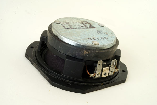
Midrange driver: JBL
LE5-12
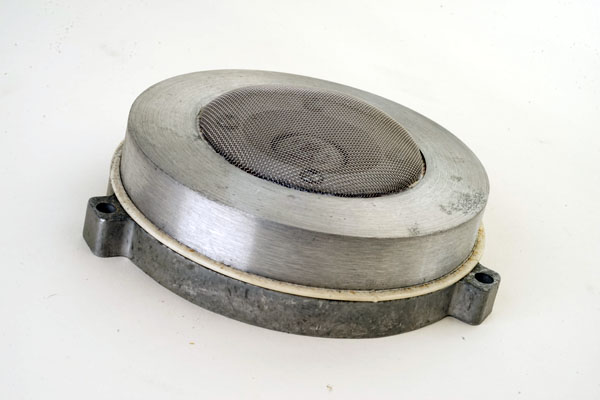
Tweeter:
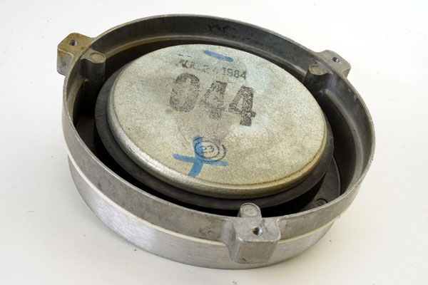
JBL 044
Driver polarity
Now, there is one thing we need to be absolutely certain of, and that's
polarity of drivers. When you apply a positive voltage to a terminal
(and negative to the other obviously) - and the cone moves
out, you have found PLUS.
Read here how you do it:
http://www.troelsgravesen.dk/polarity.htm
You cannot see the tweeter cone moving, so you have to rely on
measurements and when we apply positive voltage to the female
receptor of the terminals, this is
PLUS. The L112 is no different from the old L100
in terms of standards. JBL did not follow international standards, but
had their own strange systems.
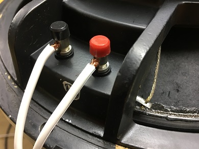
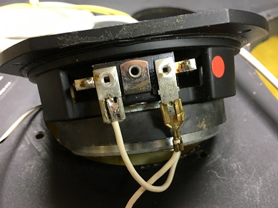
Bass: Black is PLUS (yes!) LE5-12: Male receptor is PLUS 044 tweeter: Female receptor is PLUS. Got it?

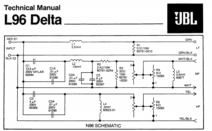
Above the L112 crossover - in fact exactly the same as for the L96 shown below. JBL didn't care too much if it was a 12" or a 10" bass driver. Hmm....well, attenuators allow adjustment of mid and treble levels, but still, the 10" bass driver must have a different frequency response compared to the 12" and require a different low-pass filter. Now, this doesn't mean the new crossover will fit your L96! No guarantee at all!
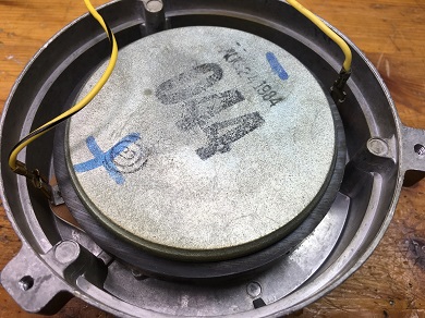
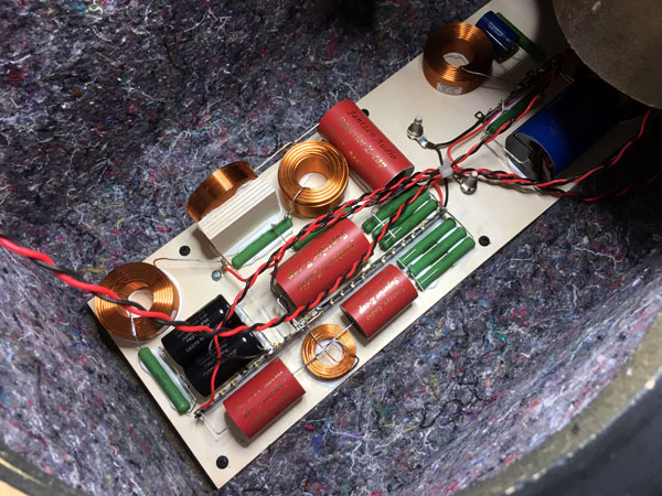
The crossover, tiny coil for the bass driver. Metallised-something caps
for mid and tweeter.
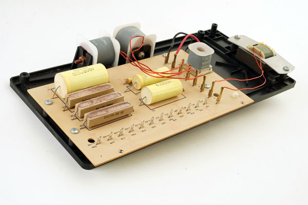
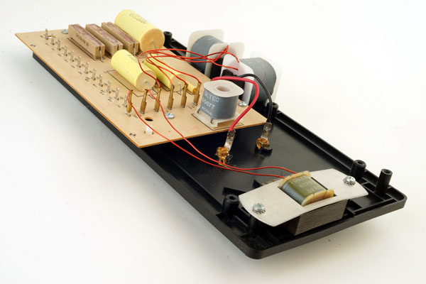
Remove the crossover panels by 6 screws on the back. Seal the two upper
screw holes.
Wind up the attenuator wires and leave them behind the mid cab not to
accidentally interfere with the new crossover, alternatively cut them
off.
The New Crossover

The new crossover is no more complex than the original. The bass section
features a 1st order low-pass function from L5 followed by R9+C5, which
is an impedance linearisation circuit to flatten the rising impedance.
The LCR circuit R14-C8-L8 takes away the 1.5 kHz peak. I've tried it on
and off, but it does help, so it stays.
The midrange follows a more regular LR topology with a 2nd order
high-pass and a 4th order low-pass due to the drivers inherent roll-off.
To match the midrange the tweeter is run from a 3rd filter providing a
4th order roll-off around 5 kHz. I tried an LCR circuit to tame the
tweeter Fs peak at 1.5 kHz but it wasn't audible, so I left it out. The
peak is more than 25 dB down, so no need for compensation.
The basic design in many ways resembles the L100 crossover. I tried a
few things to radically change the crossover design (LR2 at 800 Hz and
3000 Hz), but had to give up. This 12+5+1 design has its way of working,
thus points of crossover around 1.5 kHz and 5 kHz. This leaves all of
the midrange to the 12" bass driver - and it does it better than most
other 12" drivers due to flat cone geometry, etc.
Predicted response of drivers from new crossover.
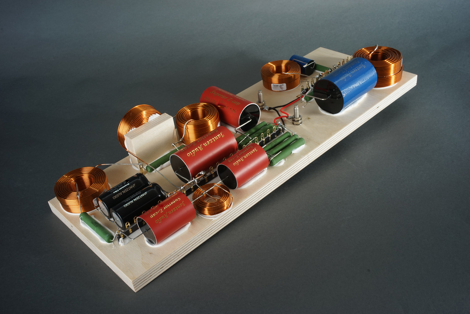
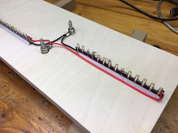
The finished crossover. Fortunately we have lots of space inside the
cabinet.
Make boards from e.g. 12 mm plywood, 150 x 450 mm.
Click image above and below to view large.
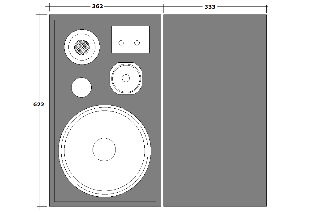
Cabinet dimensions and the use of 3/4" chipboard leaves a net volume of
approx. 56 litre minus mid cab, port and bass driver. Mid cab is rather
small and the damping materials add to the virtual volume, so let's
stick to 56 litre.
Port dimensions: Ø 75 x 150 mm, which leaves a Fp = 35 Hz (see impedance
measurement), which is a little higher than math dictates. We should
have Fb 30 Hz to reach these dimensions. Ideally the port should have a
larger diameter for a 12" bass driver.

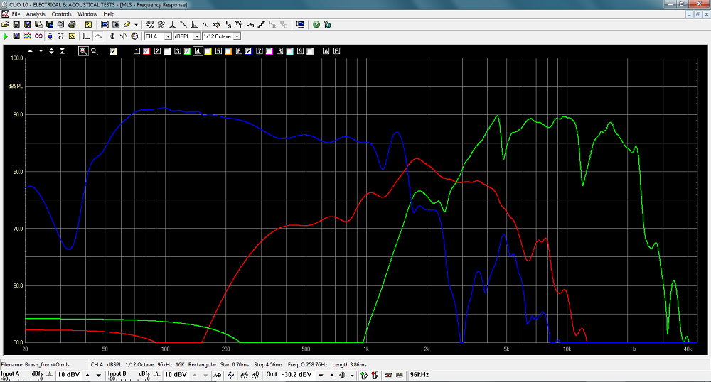
Above to the left: The drivers' response driven directly with no
crossover. Bass driver (red) displays an even response up to 1300 Hz and
a minor peak around 1600 Hz. Nothing serious.
Mid-driver (green) is not the smoothest driver seen with a serious bump
a little above point of resonance (320 Hz).
The tweeter (orange): Hmm... This is certainly not the last thing in
aluminum domes, but nothing indicated the usual 20+ kHz peak. I wonder
how they avoided this. The tweeter impedance plot (to the right) suggest
numerous minor points of resonance.
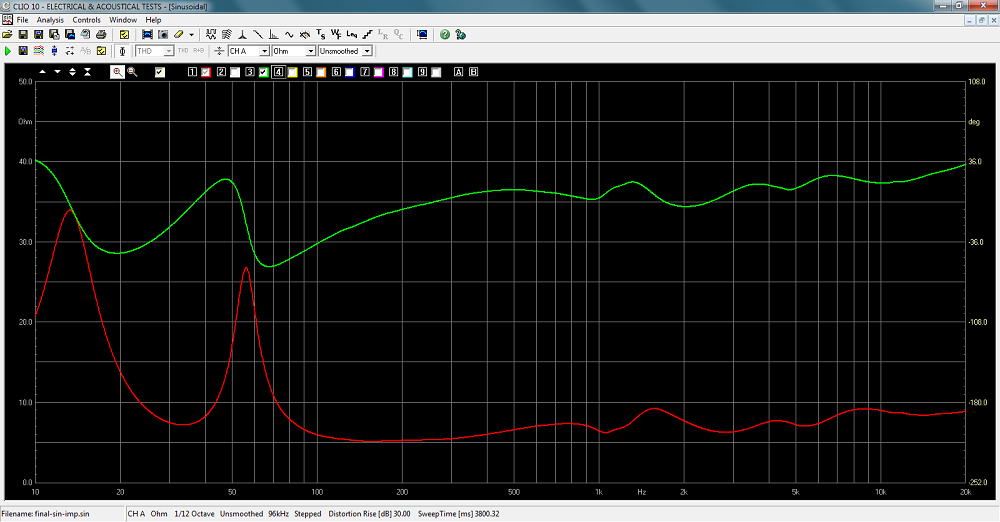
Above to the right: Drivers' impedance plot measured in cabinet. Red =
woofer with a port-tuning of 35 Hz. Midrange Fs = 325 Hz. Tweeter Fs =
1700 Hz (a rather high value).

Above the tweeter measurements. To the left the frequency response. Seems like a bunch of diffraction issues. One of tweeters have a loose grille. Below the response without the grille. To the left the cumulative spectral decay. It has to be said it has been seen better. All that said, initial listening sessions didn't point to any serious treble shortcomings. Strings and vocals came through nicely, thanks to the midrange, which handles lower- and mid-treble due to a high point of crossover.
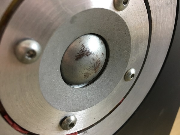
Above to the left, the tweeter w/wo grille driven from as-is crossover. No difference worth mentioning. To the right the dome. Before I had the speaker I thought JBL used the infamous alu dome, but not here. This an "alu" coated textile dome, hence no cone peak at the very high end.
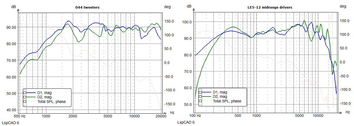
Above the two tweeters and midrange drivers from the speakers I had.
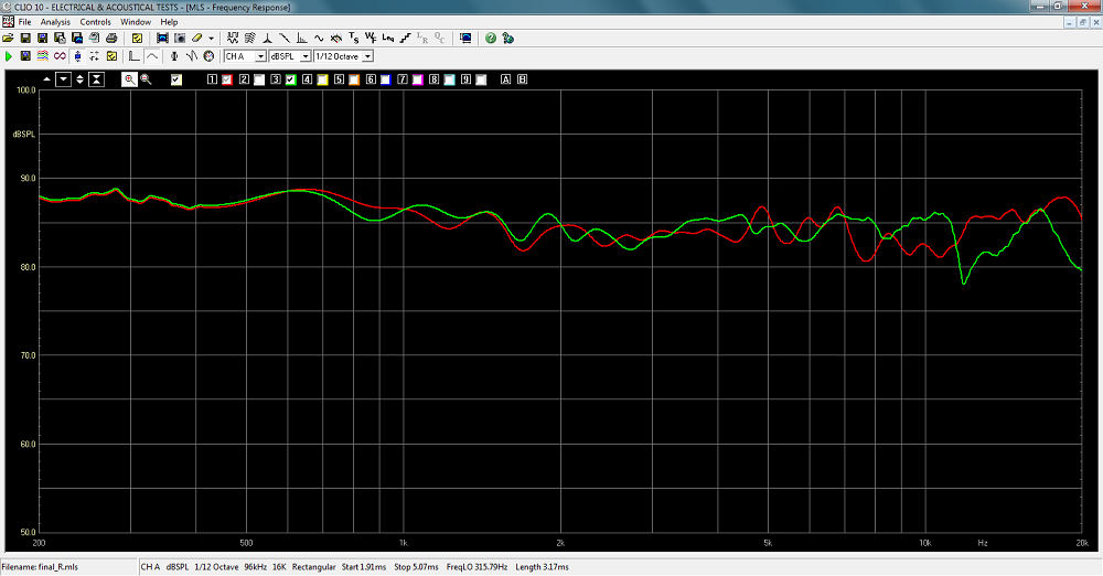
As-is
Above frequency response and impedance from M attenuation -3dB and T
attenuation -2 dB. Not too bad albeit some peaks and dips in the treble
range, but it doesn't sound nearly as bad as it may look. Impedance
profile display a healthy 6.5 Ohm minimum impedance with modest phase
shifts (green) as well. Overall system sensitivity around 88 dB/2.8V.
Above some graphs displaying mid level options.
Has to said the attenuators didn't work in some settings. Worn out.
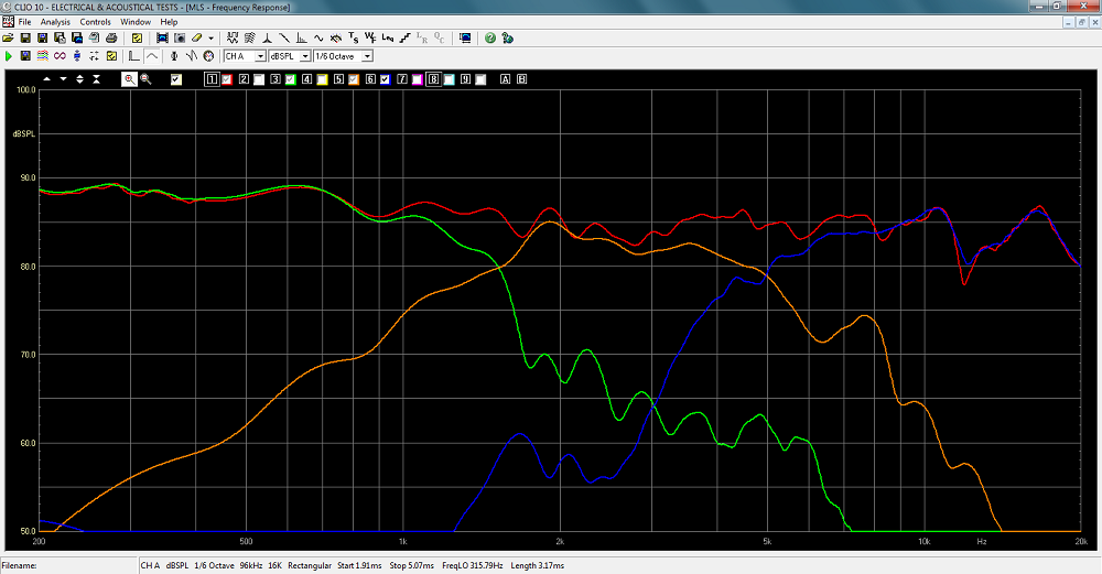
Above the response from each driver driven from original crossover with mid
attenuation set to -4dB and tweeter attenuation set to -2 dB.
What worries me the most is the un-tamed bass cone break-up at 1.5 kHz.
What the real points of crossover is for this speaker is hard to tell,
but maybe around 700 and 4000 Hz. The L112 brochure says 1100 and 3700
Hz, and so be it.
Above to the left is seen what happens when you move your head a little
horizontaly. Due to the off-set of mid and tweeter, we have some serious
crossover lobing. To the right tweeter attenuator in all positions,
well, some places the attenuator doesn't work and what we see is the mid
roll-off. Generally the tweeter attenuator has little impact on overall
level.
The attenuators will be replaced by fixed resistors in the new
crossover.
The new crossover
Above the two speakers driven from the new crossover.
Measurements are not normalised for 1 m/2.8V.
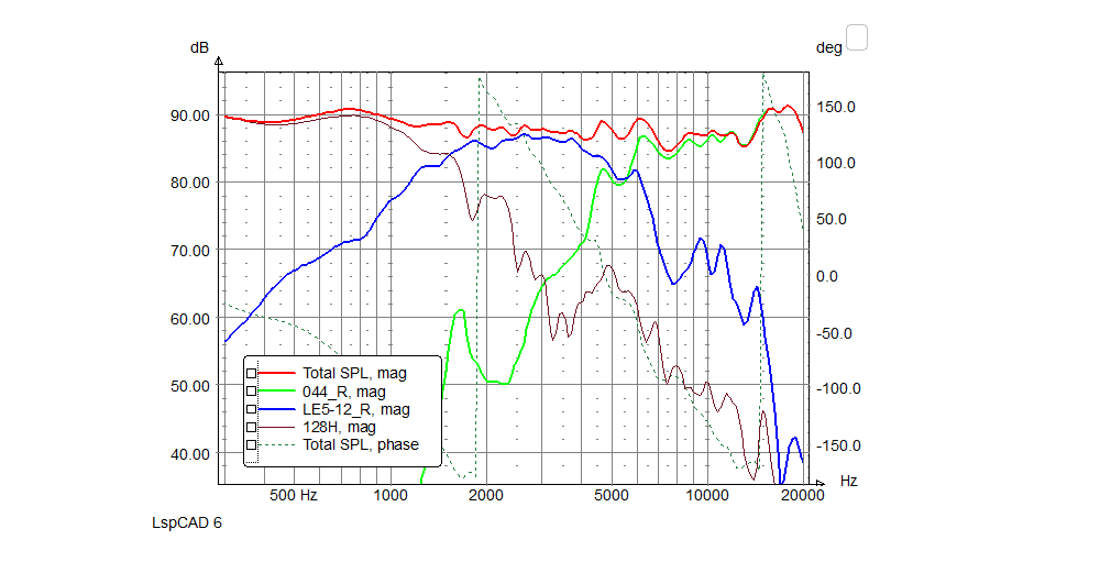
Above the response from individual drivers and summed response, all
driven from crossover.
Points of crossover around 1.5 kHz and 5 kHz.
Above the final system impedance. Even smoother than the original.
LEVEL 1 (highest performance)
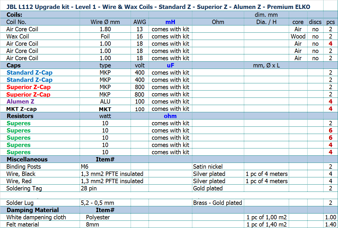
LEVEL 2
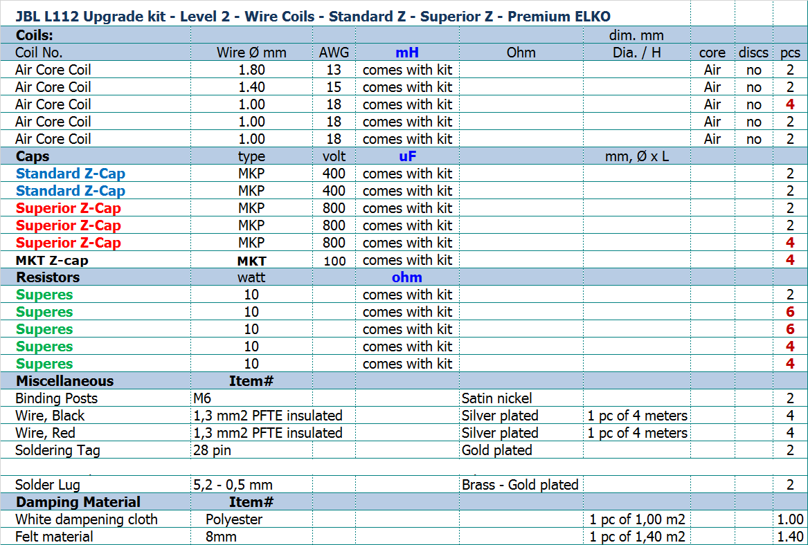
All kit and component prices may be subject to change and are always to be confirmed by Jantzen Audio Denmark.
Download Kit
Sale Presentations:

All technical questions to troels.gravesen@hotmail.com
All questions regarding purchase of kits, please mail Jantzen Audio at contact@jantzen-audio.com
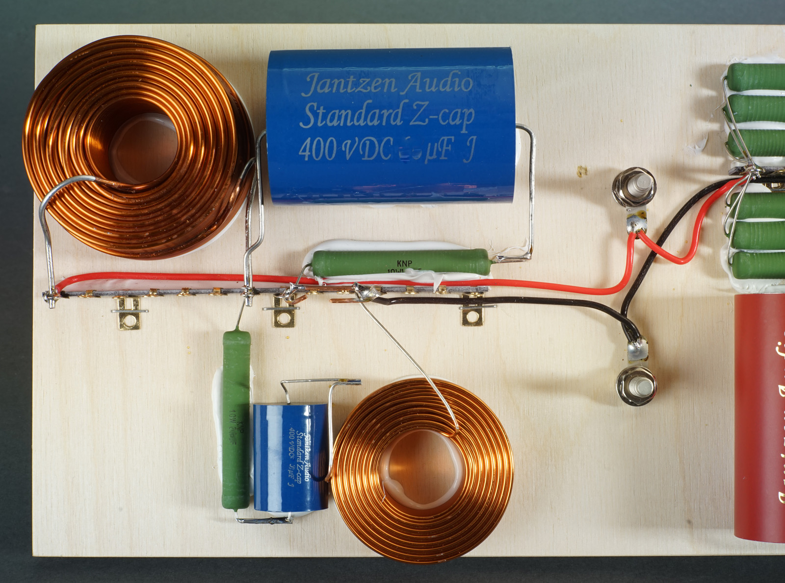
CROSSOVER-LAYOUT
BACK TO INDEX

Click image to view large
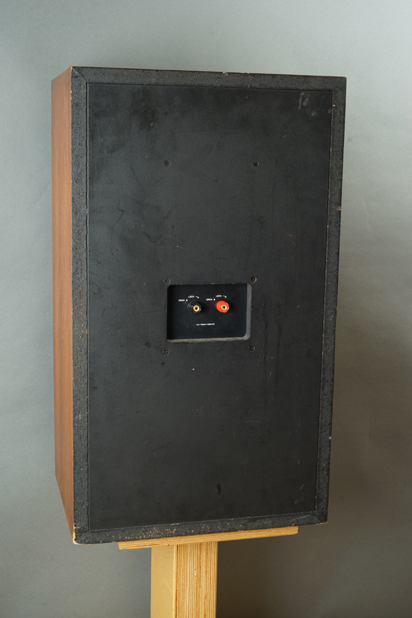
Cut a board of 450 x 150 mm and drill two 7 mm holes for terminals
180 mm from the end of the bass section. Place the board on the rear
panel and fasten with screws. Make sure the terminals hit the center of
the rear panel cut-out.
Since introduction, C6 has been replaced by new MKT-Z-caps.
Construction of the crossover board
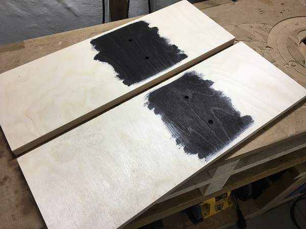
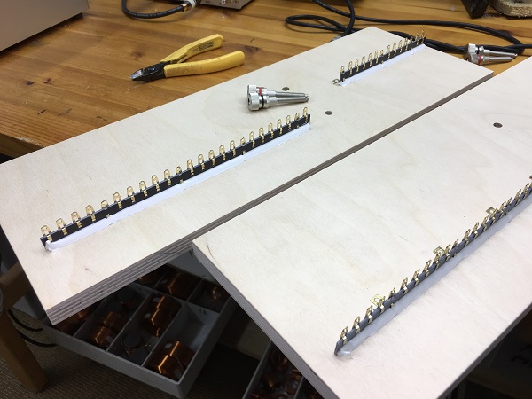
Prepare two boards: 150 x 450 mm. Drill two 7 mm holes at 180 mm distance from one end. Paint the area exposed black. Fasten the two solder tag strips like seen on layout drawing, the mid-tweeter section 42 mm from the edge and the bass section tag in the middle. The kit contains 3 solder tag strips, cut one in half for the bass section.
+ and - wires in place, ready for coils and caps.
Place components according to crossover layout. Cut a piece of the plywood used to pack the solder tag strips and use as a support for the up-right coil. Use glue to securing all components, read this: http://www.troelsgravesen.dk/tips.htm Superfix is available from Jantzen Audio. I suggest two tubes for this crossover.
Click images to view large
Mounting the crossover board and damping material
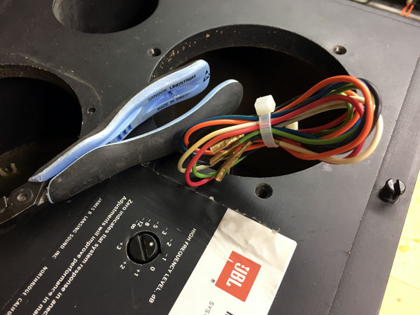
Roll up wires from the attenuators and secure with a plastic strip. Hide
behind attenuators.
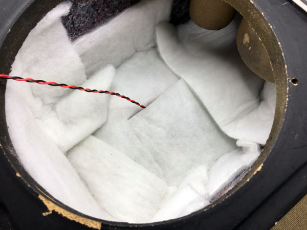
Clean the cabinet for all glass wool.
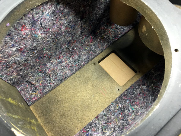
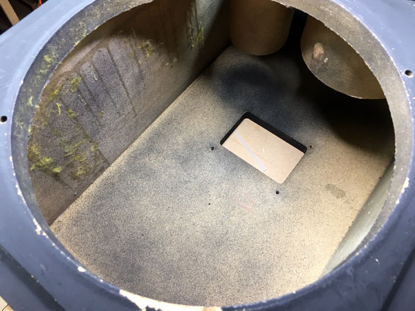
Damping:
Felt:
4 pcs 31 x 58 cm, for sides and part of rear panel (see
image above)
4 pcs 24 x 30 cm, top and bottom
2 pcs 8 x 38 cm, midrange cabinet
2 pcs Ø 110 mm for rear panel of mid cabinet
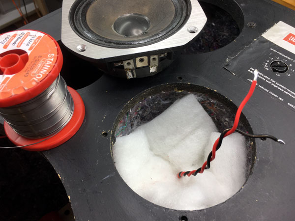
Acoustilux:
2 pcs 100 x 200 cm, fold and place
at bottom of mid cabinet
Cut residual acoustilux into 6 pieces and place one above crossover, one
at top and one at bottom of bass cabinet.
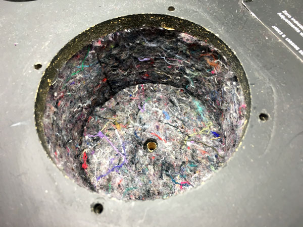
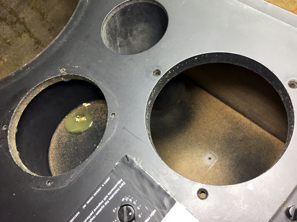
Damping of midrange cabinet. Seal the wire hole with glue:
http://www.troelsgravesen.dk/tips.htm#SEALING_WIRE_HOLES_
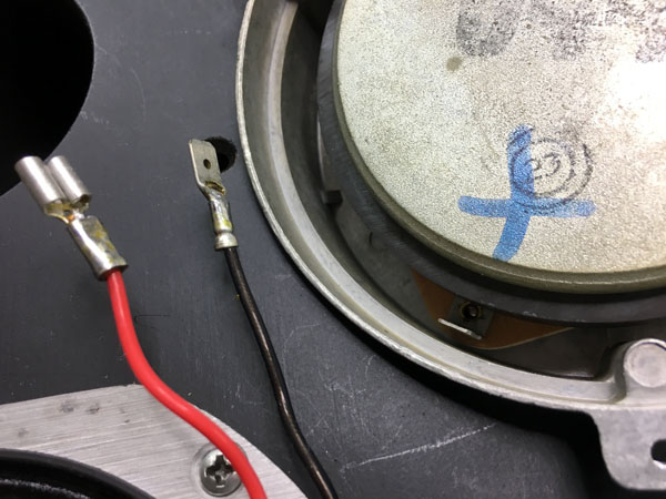
Solder plus and minus wires as seen on image above. Alternatively use
new spade lugs as for tweeter.
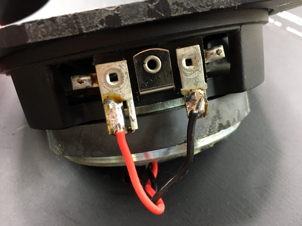
Use new (suggest) spade lugs for the tweeter. Solder rather than crimp.
Place crossover on rear panel between felt material and fasten with 5
pcs 25 mm screws.
Add acoustilux as seen on image above.
WIRING
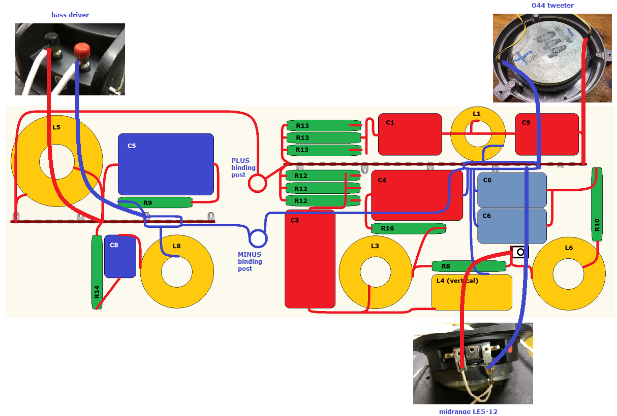
It goes without saying that connecting the drivers correctly is very important. Here tweeters and midrange drivers are connected with inverted polarity, the bass with positive polarity, that is, red to black terminal as described elsewhere. JBL can be tricky, we just need to know how it goes.