|
DIY Loudspeakers: HOME INDEX UPDATES RESPONSE WHAT'S NEW
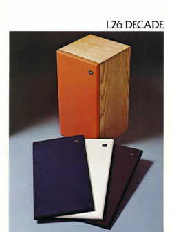
JBL L26 Decade, restoration,
up-grade
Discontinued for support from Jantzen Audio.
Link to Part II, the 3-way option.
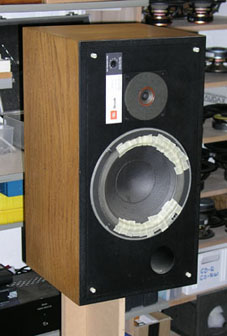
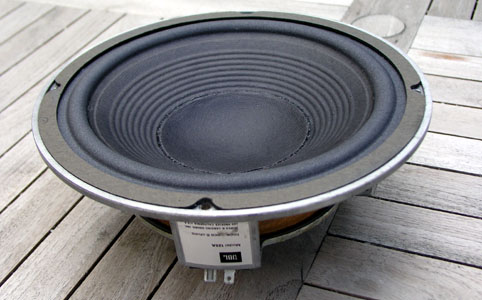
A pair of JBL L26 were
for sale at 400 DKK (60 US$) and I took the bait, well
knowing this might involve more work than first
anticipated. The foam surrounds were rotten, but besides
this everything looked fine. I should later learn that
one voice coil was rubbing in the magnet gap and this is
a problem that simply has to be solved should they ever
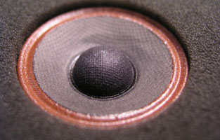
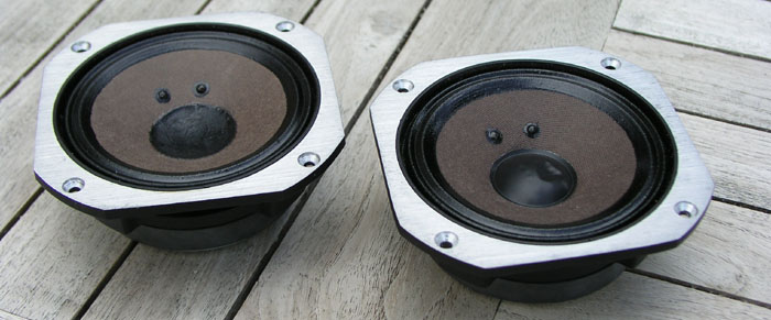
play again. The LE25 tweeters looked fine except for a
minor bump on one of the dust caps. Why bother with an old JBL speaker
at all? To put it simply: Because it's fun! The quality
build of these old JBL drivers is excellent and they hold
qualities not often found in modern drivers.
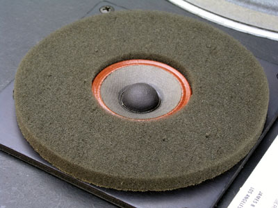
LE25 tweeter to the left. The original damping foam still in place. To the right the restored 125A driver with the new foam surround. The foam surround replacements were obtained from Speakerbits/Australia. Quite a delicate job I can tell. I've never done foam surround replacement on such a large driver before and handling the water based contact glue takes a bit of practice to get it right. DON'T use the new dust cap supplied with the kit. It's crap! This is a very thin paper dust cab that does not match the old one. Cut loose the old dust cap gently with a scalpel, clean off the old glue and glue it back in place when your work is over. I guess you really cannot get the original dust caps any more, so take great care not to destroy the old ones. They're much better. Take care not to cut through the main membrane while removing the old dust cap. I did a couple of times. It can be glued, but better not.
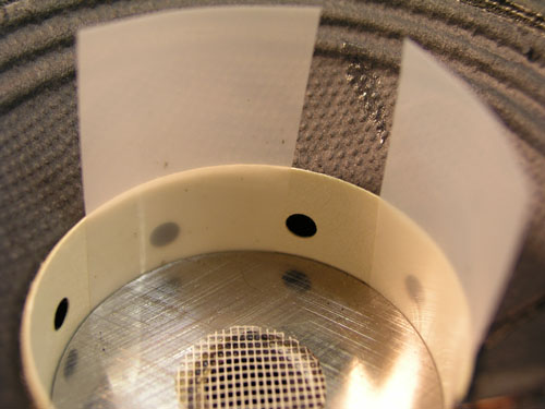
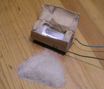
Left: 125A voice coil made from paper. Paper has some good qualities as a support for voice coils - and some bad qualities too. One bad quality is that paper takes up moisture and this speaker apparently had been stored in a humid environment causing the voice coil former to swell, creating bubbles that were rubbing against the magnet gap at high cone excursions. To solve this problem the large dust cap was gently cut loose and the cone lifted out of the magnet gap. An old JBL magnet gap is made with very narrow tolerances. Comparatively the JBL could take one single layer of the plastic sheets seen above, where a standard Scan-Speak 8545 - or similar - can take four layers! I couldn't believe it. What would happen to the efficiency of the SS drivers if they were made to such standards? But JBL drivers were made to be efficient because we didn't have 250 wpc amps back then. Right: The paper inverted domes
were cut open and some of the paper removed. Next the
voice coil was given some lacquer to stabilise the paper
and when dry the driver was driven with a 40 Hz sine wave
at +/- 6-8 mm cone excursion while some thin sanding
paper was stuck in between the voice coil and the pole
piece. In this way the voice coil surface was smoothed
and eventually could move freely in the magnet gab. The
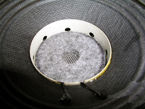
pole piece was added a piece of felt material to dampen
resonances between the dust cap and the pole piece as
seen below.
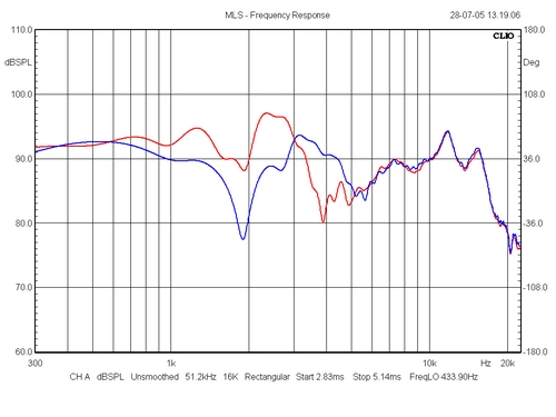
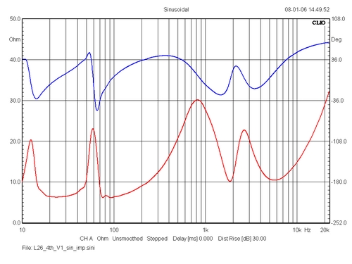
The original crossover
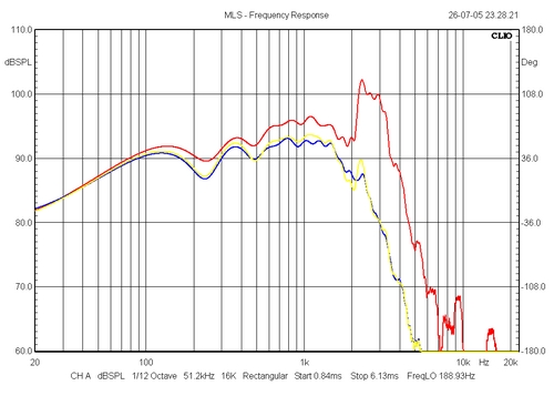
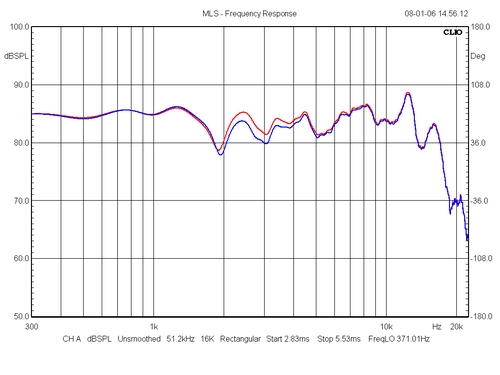
Left: The 125A driver has a major bump around 2 kHz as we shall investigate later. Blue graph above is with tweeter attenuated to give the flattest response and red is with inverted tweeter polarity. Blue is correct but the reduction of the bump at 2 kHz is really achieved by the tweeter out-phasing the bass driver. Not ideal at all. A deep suck-out just below 2 kHz Hz is the result, which can actually be difficult to hear. The overall sound is better than you would expect. Acoustic guitars sound great but vocals really do not. Right: Response of 125A driver with no crossover attached. As can been seen from the red graph, the driver has a major bump between 2 and 3.5 kHz, right where the point of crossover is supposed to be and it causes great trouble as seen from the first graph. The yellow and blue graphs are from adding some foam strips to the surround to possibly dampen resonances and so they do. Actually it's possible to make a very nice performing driver with this approach and it may be possible to add some flexible glue to the surround like seen on certain Scan-Speak drivers to cure the problem. However, I don't have the proper materials for this and I only have these drivers and won't take the risk of having to re-foam the drivers once more. A new foam repair kit is 60 AU$ + postage. And you cannot refoam drivers forever.
Simulation of original crossover. Actually this looks better that the actual measurements, but I cannot insert an L-Pad in the LspCAD programme to get the real tweeter attenuation. Here I have inserted two resistors to reach a proper level for the tweeter. Phase tracking between drivers at point of crossover is really not very good. The new crossover
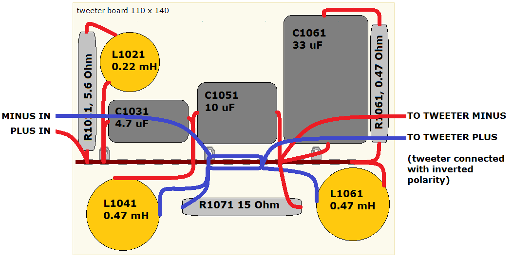
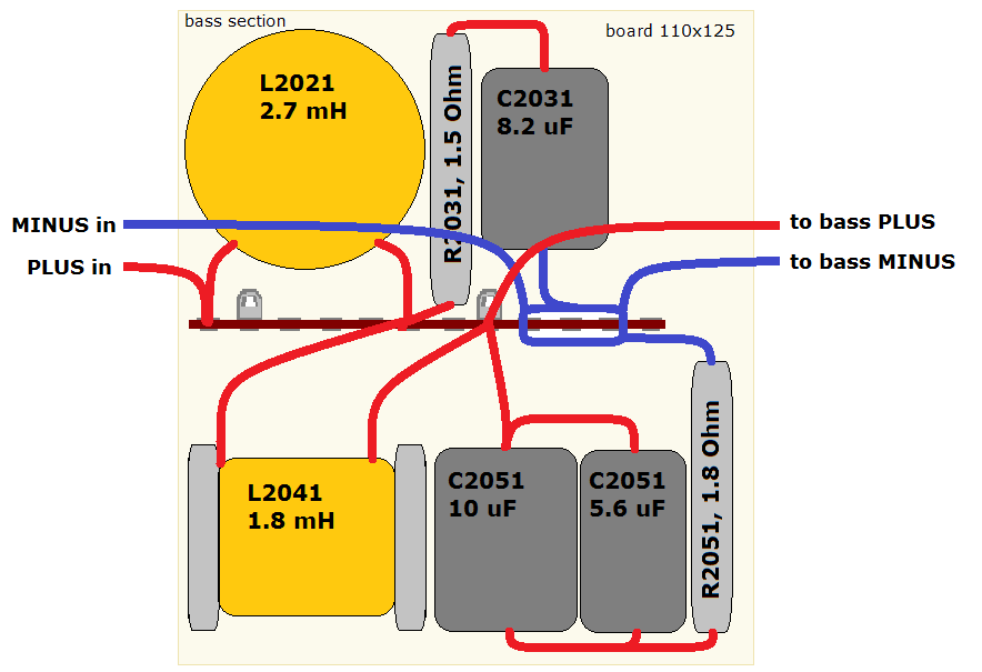
Measurements A test crossover was constructed from the above simulation and this was the result:
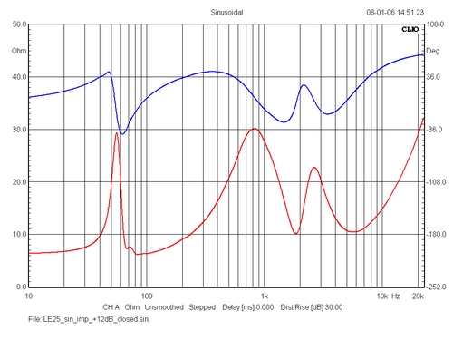
Left: - not that different from the simulation. The tweeter series resistor has been increased to 6R8. Red = tweeter notch filter coil = 0.47 mH. Blue = tweeter notch filter coil = 0.33 mH. Going from 0.47 mH to 0.33 mH makes vocal presentation a little less forward. Right: Impedance profile of modified L26. The L26 bass driver is quite unusual having a wide gap between lower impedance peak and upper impedance peak in the 20-100 Hz region. This driver really is best suited for closed boxes. So, here we have the impedance profile from stuffing the vent:
Reversing the polarity (=
same polarity) did not produce the well known nulling
effect. In the simulation soft-ware it does, but here we
have a large membrane (bass) producing all frequencies up
to 1.5-2 kHz and the relative distance between the
acoustical centres of the bass and the tweeter will take
any measure from 10 to 30 cm and the depth will vary also
whether the sound is coming from the centre of the 125a
driver or the membrane close to the suspension. Sound: Well, if you like your L26s and still have some foam surround intact - or have chosen to have the drivers refoamed, I'd say a new crossover is definitely worth while. The level of transparency is much better than I had anticipated, the overall tonal balance is much enhanced and the L25 tweeter is actually a very decent tweeter. The speaker is not as sensitive as shown in the simulation, rather around 85 dB/2.8V, but it's a speedy and engaging speaker. The 4th order filter allow you to listen at a wide angle without loosing contact with the music and quite remarkable; you can listen at very low levels and still hear what's going on.
Not supported by Jantzen Audio
any more.
All technical questions at me: troels.gravesen@hotmail.com Check this out before start making crossovers: http://www.troelsgravesen.dk/tips.htm#CONSTRUCTION_OF_CROSSOVERS http://www.troelsgravesen.dk/LCR-RC.htm
Find your drivers' polarity this way:
The L26 3-way option, Part II A pair of JBL LE5-12 middrivers
were available and appear quite similar to the LE5-2
except for the ceramic magnets. And an alu dust cap.... I
don't like alu dust caps on top of a non-damped pole
piece. Off it goes and in comes a paper dust cap from some
old drivers I have stripped. The dust caps were given a
coating from the glue used for the re-foaming job. This
glue does well for coating purposes too. Dilute with
water until suitable consistency and apply a thin layer
to the dust cap.
So, a 3-way calls for a complete re-build of the L26 enclosure. New front panels have to be made and the old cabinets stripped for everything including the poor binding posts. The cabinets - having a nice oak veneer - will be sanded and given a new oil rub. Bracing will be added to reduce cabinet resonances. Rebating for drivers with a square or cut-off chassis is trouble, but worthwhile and has to done to enhance performance. Go to: |