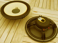
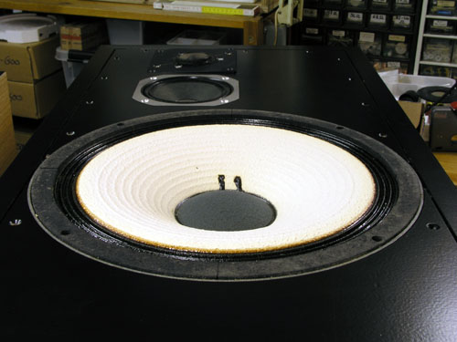
The JBL Kit is
doing well and it's time to assemble my
own "L100" from my eBay purchases. A
true L100 box replicate it won't be because the
123A bass driver can do better compared to the
original 44 litre vented box. As can seen in the JBL-Kit file,
box simulation is not an easy exercise due to the
driver's low electrical and mechanical damping,
i.e. high Qe and Qm. We have a 3-4 dB bump in the
50-100 Hz region, thus cab volume has been
increased and the vent is gone, being replaced by
two Variovents to produce an aperiodic system.
The JBL
Heritage website is the
place to go if you want more info on
this classic speaker, and I've read the L100 box
being characterised as a solid, well-built
construction. It isn't. Well-built yes, but
solid? It's a boom box made from chipboard with
no bracing at all. Put your hands on the cab when
played loud and you'll feel it's highly resonant
likely to cause some midrange smearing and lack
of detail. The JBL
L26-3way project left no doubt
about the advantages of adding braces. The
performance at all frequences will benefit from a
non-resonant cabinet.
An option is to rebuild the L100 cabs like the
L26-3-way. A new front panel with drivers placed
symmetrically is a must if you choose to do this.
Building new cabs was a
pleasant deja-vu, a straight forward
rectangular box like I did many times during the
Seventies, only this time braces and bitumen pads
were added. I've recently bought a cheap 1800
watts Chinese table saw and I should have done
this years ago. I takes little space and after
adjusting almost everything - you don't get a
plug'n play unit for 300 US$ - plus installing a
new high-quality 60-teeth blade, it cuts
pre-veneered 22 mm MDF like butter, leaving razor
sharp edges ready for gluing.
Actually these cabs are
meant for more designs (SEAS
W26-Classic), so 20 x 20 mm pine
fillets were added to support rear and front
panels, allowing various drivers, vents and
Variovents. 22 mm pre-veneered MDF was used and
side, top and bottom panels were cut 45 deg. to
allow nice looking joints. Only drawback with
pre-veneered MDF is that you have to take great
care during the rest of the construction work to
avoid nicks and cracks. The rear and the front is
going to be painted black and if you think
veneering is tedious, try painting! Lots of
sanding, priming and several coats of paint.
Takes quite some time.
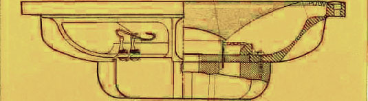
Cabinet drawings
Inner dimensions given
here are only guidelines.
Dimensions on braces have to be adjusted once the
outer cabinet is in place.
|
Box simulation (once again)
123A
bass driver in original 44 litre cab @ 30 Hz port tuning.
We have a ~4 dB bump at 70 Hz = boom-bass.
123A driver in new 65 litre closed cab. The 70 Hz bump is
2 dB down.
Above is seen 123A driver in 44 litre original vented cab
compared to 65 litre closed cab, x-over (kit) attached
for both.
What the Variovents are going to do to this has to be
seen. It can't be simulated properly. My guess is that
the bump will be further reduced and we'll have a little
extra bass below 30 Hz; the latter I really don't think
matters.
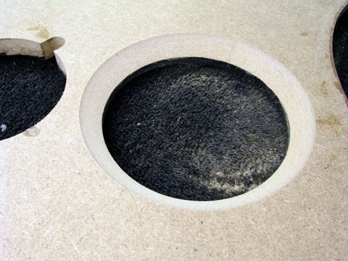
The
acoustic vent
May
2014: The Variovent is out of production but you can
still get the same thing from using a conventional port and
stuff it lightly with acoustilux. I suggest a 68 x 200 mm port (Jantzen
Audio). Cut it to 10 cm length. Now, the question is how much
acoustilux should be added? I suggest for a start rolling a 10 x
20 cm piece of 30 mm acoustilux at insert it into the port. If
you can do an impedance plot you add damping material until you
get the same impedance profile as can be seen below. If you
cannot perform measurements, you have to tune by ear. No damping
will make a boomy bass peaking 4 dB at 63 Hz from a 65 litre
cabinet and Fb = 30 Hz. Stuffing the port really hard (closed
box) will reduce the bump by 2 dB. The full length - non-stuffed
- port (20 cm) will make a Fb = 22 Hz. Try it out.
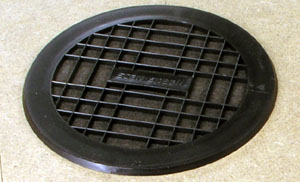
The Variovent consists of
two grilles with some damping material
stuck in between. Simple as that. The diameter,
amount of damping material and the compression of
the material determines the air flow properties =
acoustic resistance. The late Gilbert Briggs
(Wharfedale) made slits in the rear panel and
added damping material over the slits. Works the
same and costs nothing. But you have to be able
to follow the impedance of the system to tune the
amount of damping material needed.
The Variovent is a device
sometimes causing much debate. What is an
acoustic vent? Well, an acoustic vent allows some
ventilation at low frequences and virtually none
at higher frequences. So what's that supposed to
be good for? Neville Thiele studied the Variovent
in detail and concluded it didn't offer any
advantage over a properly designed vented
systems. The general advice on the use of
acoustic vents is simple: Try it! Which offers
little comfort to those addicted to math. But box
calculation based on Thiele/Small data really
only apply for speakers with a Qt = 0.35, which
only counts for very few drivers. Based on
experience we use speakers with high Qt in cabs
too small and drivers with low Qt in cabs too
large compared to strict box simulation.
Comparing the impedance
peaks of a driver in free air and a
perfectly closed and empty box should reveal the
same peak height, so we have no loss in the
closed box. Obviously the resonance frequency
is higher. Adding damping material to the closed
box we see a decline in peak height; now we have
some loss. Adding an acoustic vent may produce a
significant reduction in peak height depending on
how open the vent is. So, the system Q-value is
lowered (= more loss) from applying an acoustic
vent although we really can't speak of a Q-value
of an aperiodic system. Basically a closed box
has 2nd order roll-off, a vented system a 4th
order roll-off and the aperiodic system a 3rd
order roll-off.
|
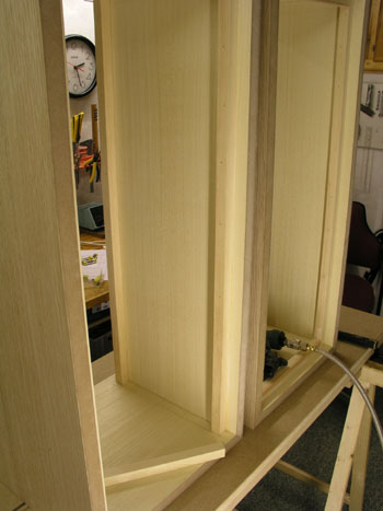
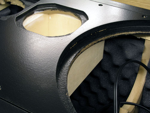
Pics from cabinet construction
.jpg) .jpg)
Cabs assembled and waiting for bracing and
front/rear panels. Addind bracing after assembling he
cabs may seem odd, but if you don't have
CNC cut panels, accurate down to +/- 0.1 mm, you need
some freedom before to adjust bracing, fillets and
front/rear panels.
.jpg) .jpg)
20 x 20 mm pine fillets are used to
support front and rear panels.
 .jpg) .jpg)
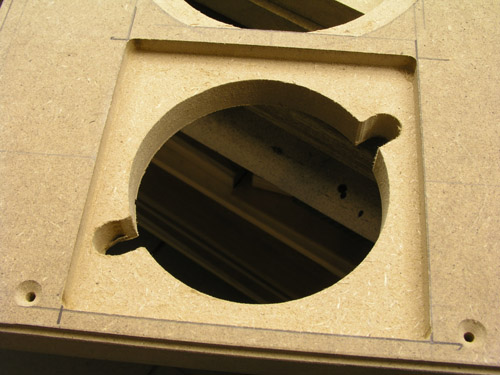
.jpg) .jpg)
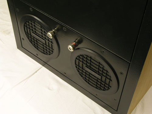
Rear panel is devided into two section in
order to allow Variovents and traditional ports.
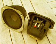
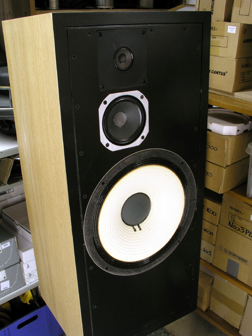
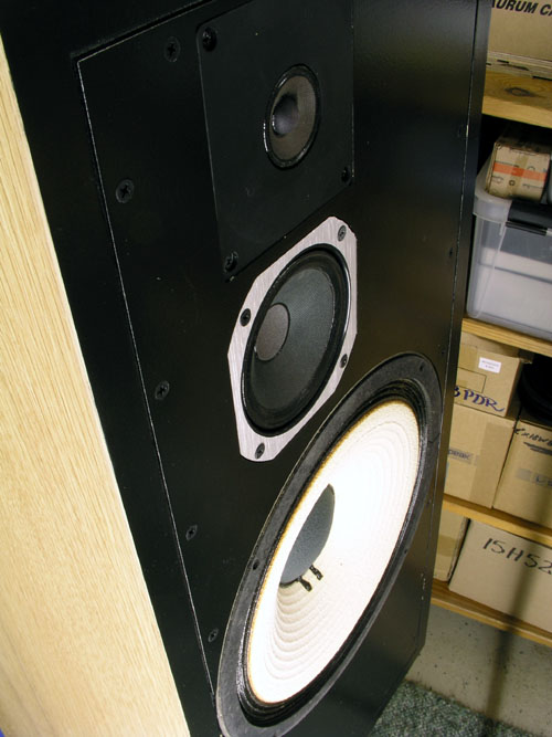
The mid and the tweeter -
Both tweeter and mid will
be flush mounted. Yes, it's trouble due to
truncated mid frame and the square tweeter
faceplate. But take a deep breath - and a couple
of hours later it's done and they look so much
better - and performance is enhaced too as we
shall see later. The mid needs a 5 mm rebate and
the tweeter 7 mm. The LE26 tweeter will be used
in this construction but the LE25 (brown
surround), LE25 (black surround) and LE25-2 (also
black surround) will be tested too to see if
there are any differences that will need
crossover modifications.
As seen in the LE26
article, the conveks plastic
faceplate isn't good and the tweeter performs -
technically - better if we turn the faceplate
upside down. This doesn't look particularly good,
so I going to make a new faceplate for the LE26
as described in the article. 4 mm thick as seen
below. The tweeter faceplate is 3 mm, additional
faceplate = 4 mm, thus 7 mm rebate as seen above.
Alternatively a 5 mm polyester foam
"faceplate" may be used. I suggest
cutting a 108 x 108 mm piece of polyester foam to
cover the rebate if this is your choice.
|
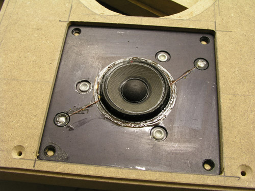
See, the LE5-2 really looks good this way.
The LE5-2 needs deep chamfering to allow
free ventriation.
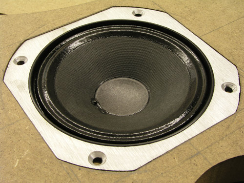
Mid cabs
Left: I used 12 mm baltic birch to make a cab of 130 x
130 x 75 mm inner dimensions.
Right: Testing driver rebates.
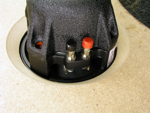
Damping
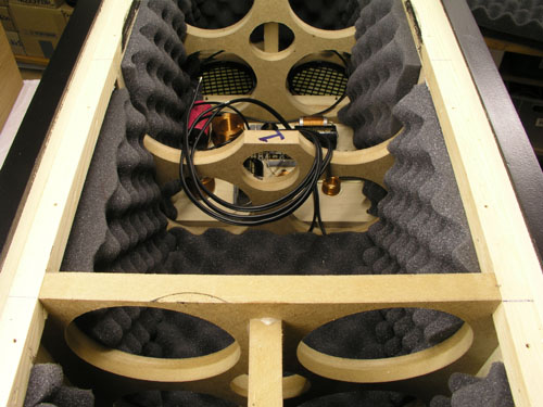 
Left:
4 mm bitumen pads were applied to all internal panels and
on top of this 40 mm egg crate foam.
Above the crossover two layers of 30 mm acoustilux.
Right: The Variovents and binding posts.
First time set-up with LE26 tweeters. No changes to the
crossover. High value of tweeter shunt resistor, R1061,
was chosen.
Crossover
No change to the crossover from
the up-grade kit.
The
crossover allows the use of LE25, LE25-2 and LE26
tweeters.
As always: Do take time to try out attenuation of
tweeter and mid-driver:
Mid: Try bypassing R 2011 and hear what happens.
Tweeter: Try the two options of R1061 and hear what
happens.
Check out the various crossover kit levels
here.
Measurements
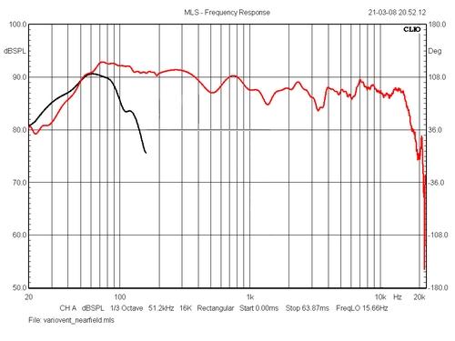 
Left: Red = SPL @ 1m/2.8V. Black =
nearfield response of Variovents. As expected the
Variovents add a little to the 20-40 Hz output.
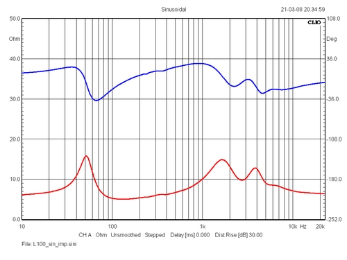
Right: Impedance of system. Now, this is an easy load.
Minimum impedance is 5.0 ohm and phase angles are modest.
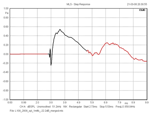
Step response. With a 5 deg. tilt the bass
and mid are close to being time-coherent (1st order
filter and tilt)
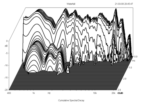 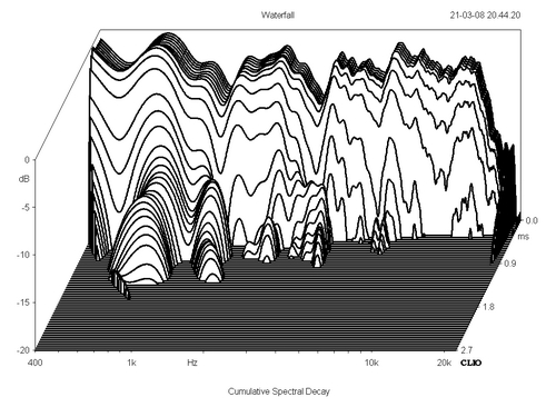
Right: 20 dB cumulative spectral decay of
2007 set-up (LE25 tweeter). Right: 2008/LE26 set-up.
I wanted to see if the heavy bracing and panel damping
would decrease resonances in the midrange and in
the 400-2000 Hz region something has happened.
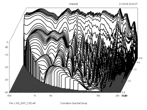 
40dB CSD 2007 (left) vs. 2008 (right).
Now, 40 dB really is too much to show, but the CLIO
doesn't allow 30 dB, which would be more appropriate.
What is clear is that the vastly enhanced midrange from
the new braced cabinet is not fully revealed in these CSD
presentations.
Measurements are tricky business and basically tells
terribly little about the sonic performance of a speaker.
Bass performance from new cabinet
Making plans
for my own L100s I had two things in mind:
Transmission line and the Variovents. Both would
suit the high Qt 125A bass driver. A transmission
line would require at least a 100 litre cabinet
and I wasn't prepared for this, thus the
Variovents. They did very well with the L26-3-way that I
wanted to use them again.
The bass performance
bears little resemblance of the former boomy bass
reflex loaded 123A driver. It's deep, firm,
tight, solid and the Variovents allow a shallower
roll-off and despite the 50 Hz system resonance.
The renovated L100 handles bass noticeable
different from vented designs of similar size,
e.g. Ekta Grande. Running test warble tones at
20, 30, 40 and 50 Hz produce a smooth steadily
increase in response and I think the best way to
describe the bass quality is that it is doesn't
change character over the whole bass region,
30-160 Hz, except for amplitude in the lower
octave.
|
The sound
|
The
JBL L100 Century loudspeaker was a
worthy representative of the Seventies
tizz-and-boom tradition. It had both. Loads of
bass from a high Qt driver in a too small vented
cabinet and loads of tizz from the 6.5 kHz
peaking of the LE5-2 middriver. Very charming -
and impressive - at first "hear", but
tiresome in the long run. Placing these three
high-quality drivers in a vibrant chip-board
cabinet only made things worse as the bass driver
was meant to handle most of ever so important
midrange. The result was a smeared midrange
garnished with an aggressive treble from all
three drivers trying to do the same thing,
playing treble. No wonder later JBL monitors had
more sophisticated crossovers, usually 2nd order.
There's
one thing that adds a specific character
to this speaker: Having a 12" driver
handling the midrange up to around 1-1.5 kHz.
It's kind of studio sound. Professional studios -
and cinemas for that matter - often use huge
driver for midrange. Why? To reduce distortion
obviously. We're so sensitive to distortion of
the human voice and a proper designed 10-12"
driver can do things here that no 6" can
ever do. Due to the ingenious flat cone geometry
of the 123A driver, this goes better than for
most 12" drivers. I guess the heavy coating
of the 123A driver is part of the secret,
reducing potential cone break-up to acceptable
levels. The price to pay was reduced efficiency.
The calculated efficiency of the 123A driver is
around 89 dB, well in accordance with actual
measurements.
Playing
Nils Lofgren, Acoustic Live, leaves no
doubt that we really do need a 12" driver to
fully enjoy his powerful guitar play.
More
impressions to come.
|
The L100
Crossover Up-Grade Kit
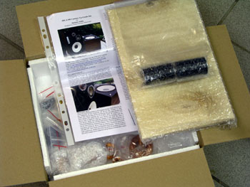
The complete kit
(a pair) includes:
1. Terminals.
2. Two extra resistors for tweeter attenuation.
3. Soldering tag strips.
4. All crossover components: Baked non-resonant
coils, all polypropylene Cross Cap capacitors,
MOX resistors and cables for connecting drivers.
5. Kit instruction containing crossover
schematics, a short version of first article and
large sharp photos of the assembled crossover
board.
Not supplied is silicone glue,
screws and damping material. It's highly
recommended to replace the old damping material.
The kit price is set at a level where you
cannot buy similar quality components at a lower
price from any supplier.
Orders at:
contact@jantzen-audio.com
When placing an order, please include full name
and shipping address.
Kit instruction.
Download kit
prices, pfd file
|
Response from
people buying the up-grade kit
|