|
The implementation of
parallel LCR, RL and RC circuits in crossovers
First of all, all components use in my
crossovers are bi-polar, this means there is no "in", nor "out". They can
be connected in whatever way suits the layout best. Music is AC, not DC,
so there is as much signal coming one way as the other.
A very common question to my crossovers is why my layout differ from
schematics., i.e. why is the RC circuit turned up-side down or why is
the LCR circuit components in a completely different order.
The short answer is that circuits parallel to the driver can be put
together in any order, being RC or CR or LCR, CRL, LRC, etc. They do the
same thing regardless of order.
An RC circuit across a series coil can be placed in any order - it does
the same thing.
However, RC and LCR circuits MUST be at the same spot in the signal path! Do not move
an RC or LCR circuit to the other side of a series capacitor or series
coil! Then terrible things will happen.
An RC or LCR circuit in parallel to the driver can be implemented in any
order; it does the same thing: It absorbs energy at certain frequencies
being a harmonic oscillator in technical terms.
In my LSPcad
simulation software I may place components in random order, but
when it comes to the actual crossover layout it may prove
beneficial to change the order due to size of the components and to get
coils as far apart as possible to reduce interaction, given the space
constraints of the crossover board.
Hope this helps :-)
Examples:
RC and RL circuits:

Above an RC circuit across a series coil.
The RC circuit can be placed in any order. Does the same thing.

Above the midrange section of the Jenzen-D
speaker.
After the series capacitors we have an RL circuit smoothing the roll-off
of the midrange drivers towards lower frequencies.
Below you can see the same crossover where the RC circuit has been
turned up-side down.
L2021 and R2021 turned up-side down. It does the same thing.
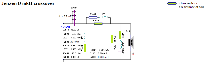
LCR circuits:
Above is seen an LCR circuit, a notch filter,
suppressing a peak in the treble range of the middriver.
The values of the components are tuned so that we have a smooth roll-off
of the middriver towards higher frequencies.
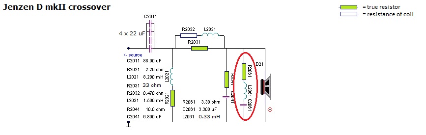
Below you can see the same LCR circuit in different order, e.g CLR (from
upside down) or LCR. It could also be LRC.
It does not matter. It does the same thing regardless of orientation.

It can be like this, or -
- it can be like this. The LCR can be CLR, RLC, etc., same thing.
|