|
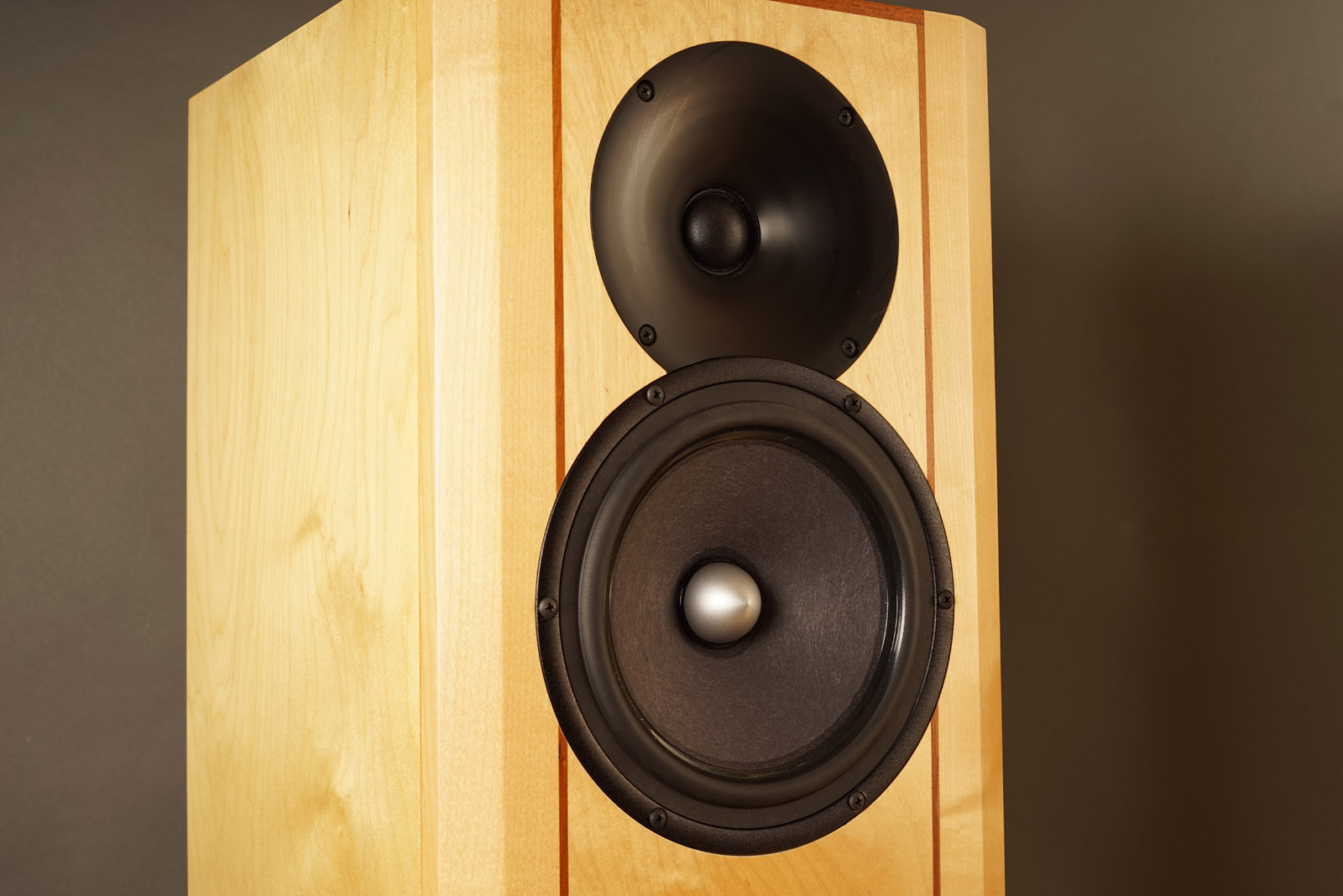
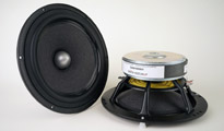
QUATTRO mkII is the
up-dated version of the original QUATTRO based on the JA8008
driver, here with the new
JA8008-HMQ
driver. There were only a few changes to the crossover and only
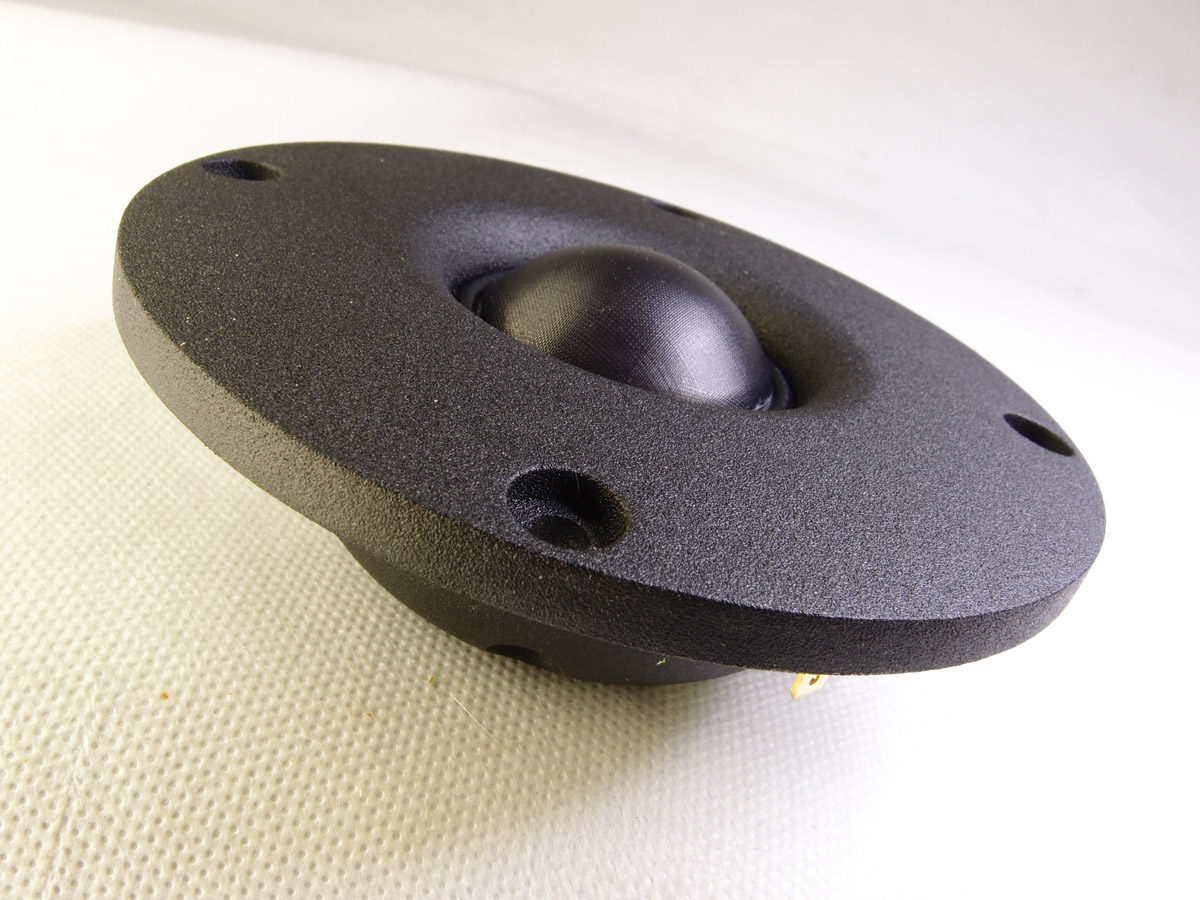
to the low-pass section of the bass driver. The SEAS T35C002
tweeter is noiw standard.
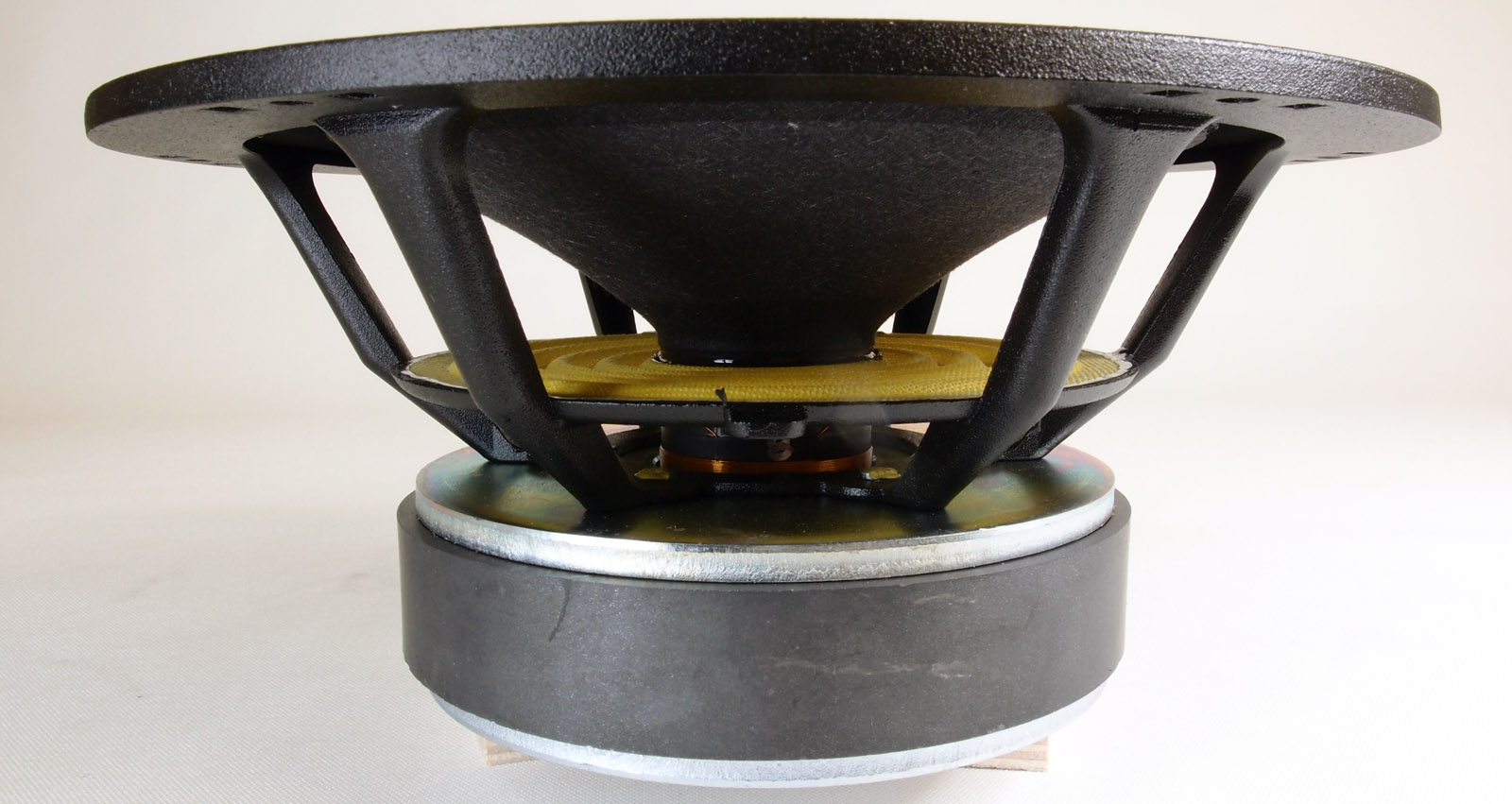
With the new JA8008-HMQ driver the performance is further
increased by a more tight bass and enhanced midrange
transparency. QUATTRO is a true 8 Ohms speaker with a minimum
impedance of 7 Ohms and suitable for medium power valve amps.
QUATTRO was the forth construction based on
the JA-8008-HMQ/SEAS T35C002
high-efficiency drivers, thus
"QUATTRO". The other
constructions are TQWT mkII, DTQWT-mkII and OBL-11
with the up-dated mkIII versions
here.
Quite a number of people have asked for the JA8008/T35C002 sound
in a smaller cabinet and there are a few issues to address when
doing so. The JA8008 driver is a low-Qt, high-efficiency driver
and not directly suitable for small vented cabs unless we
sacrifice some bass extension or system sensitivity. If we
target F3 around 40-45 Hz from 40 liter vented enclosure, we
have to sacrifice system sensitivity and settle for some 90-91
dB sensitivity.
To equalise the response of the 8008 driver, a baffle step
compensation circuit may be used, simply consisting of a coil
bypassed by series resistor. From thereon we can start modelling
the response of the two drivers to make a point of crossover
similar to what is used for the TQWT/DTQWT/OB9.
I have added measurement
files on another page as measurements in
reality tell close to nothing about how a
loudspeaker actually sounds. What we can get from
measurements is a good idea of what amps may be
needed, roughly an idea of the tonal balance of
the speaker and we may get an idea of bass
extension too. The QUATTRO is tuned more flat
compared to TQWT and DTQWT and I won't hesitate
to recommend the speaker also for recording
studios, although I know these guys sometimes
listen to the weirdest things. They may listen
for specific qualities in a recording requiring a
lot on linear distortion, but what I can assure
from this speaker is a linear response with tons
of detail. It does
Siri's
vocal very well and it does all the
acoustic instruments as well, like the flute,
oboe, violin, piano, which I use for voicing a
speaker.
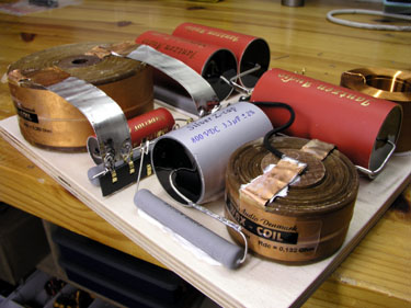
Drivers and components
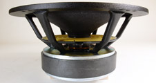
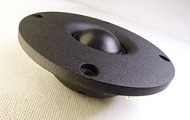
Click
images to view large.

Click image to view large
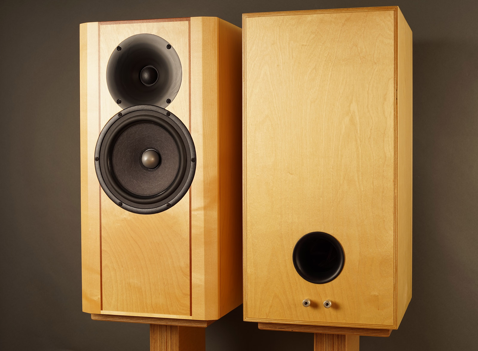
Cabinet
Back
to top

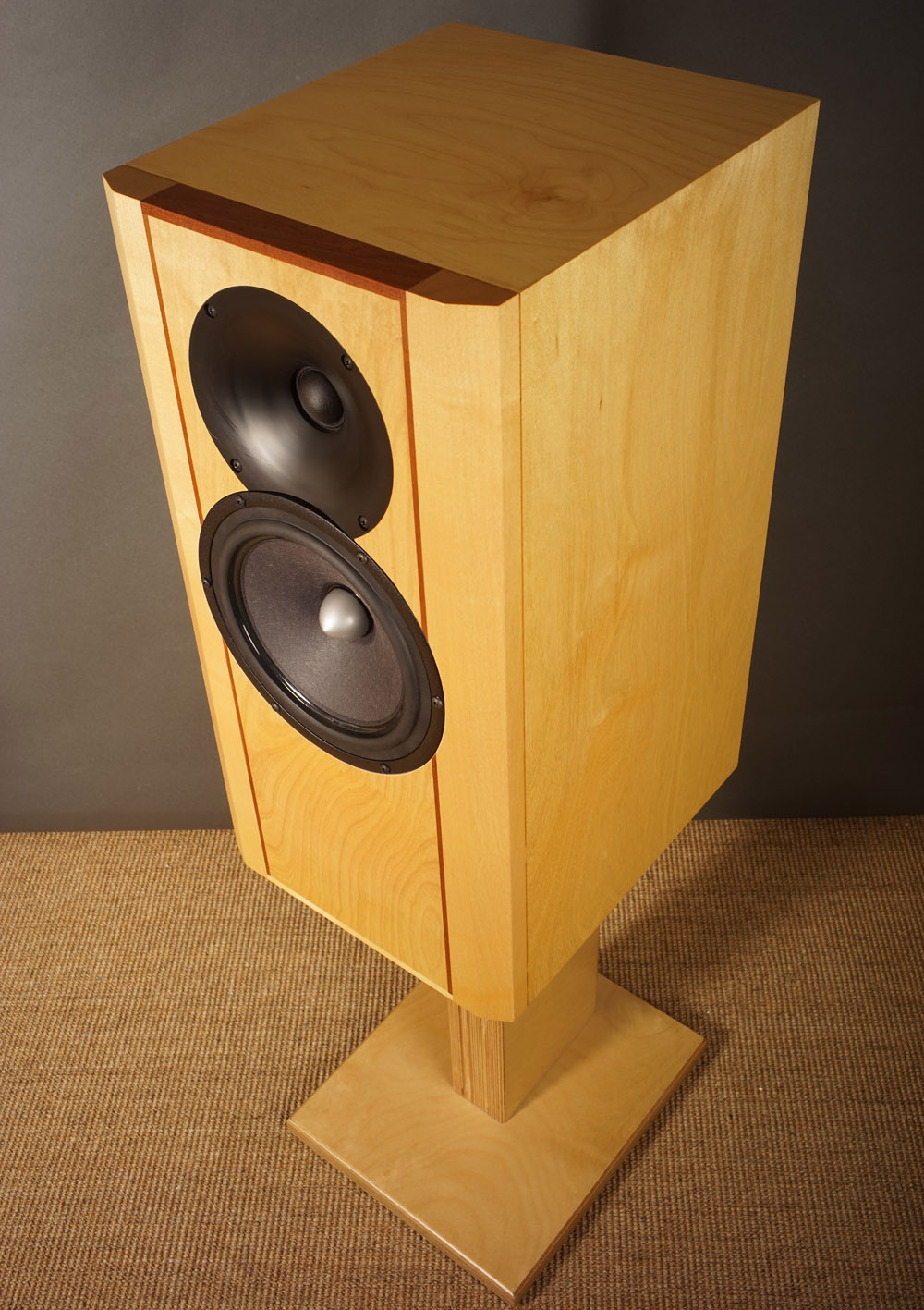
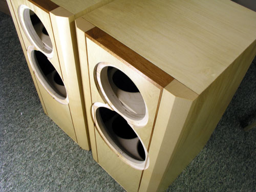
Cabinet made from
22 mm MDF, except for front panel (30
mm), should make 2.56*2.98*5.56 = 42.4 liter net
volume. Adding bitumen pads, port, braces,
drivers, etc., will further reduce volume a liter
or two. Do not be too keen on this, anything from
38-42 liters will work perfectly as long as front
panel dimensions and driver placement is
maintained. For my cabs I used 21 mm Baltic birch
and 30 mm for the front panel laminated from 21 +
9 mm sheets. Front panel fillets are made from 30
x 50 mm solid maple wood.
I often have the question
whether Baltic birch is better than MDF and I
honestly can't tell. I never made two pairs of
speakers from both materials to compare sonic
impact. From a well-braced cabinet added bitumen
pads, I don't think there will be much
difference.
I use Baltic birch as it gives me the final
finish without having the trouble of applying
veneer - and I just happen to like the appearance
of lacquered Baltic birch although it's not an
easy material to use. Read below.
The QUATTRO need stands.
To my ears - and sofa - 45 cm height. I listen to
the QUATTROs slightly toed in and as usual in my
living room, 1 meter from the front wall and ~1.8
meters from side walls. My speakers are placed on
the long side of the room, thus very little
roomgain.
Go to cabinet
constructions pics
BOX SIMULATION
Click
image to view large.
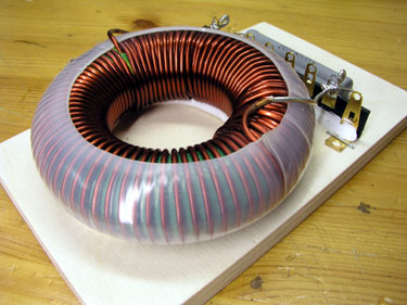
To reduce system sensitivity some 4-5 dB compared to TQWT
and DTQWT, a 3.9 mH coil bypassed by ~3.3 ohm is used.
Eventually during fine-tuning, R1011 was set to 5 ohms
consisting of two 10 ohms (10 watt) resistors in
parallel.
We do burn some energy here and we want R1011 (R2011 in
schematics below) to stay cool.
The port:
Fb = 36 Hz, port
dimensions: 68 mm Ø x 112 mm length
(don't change the supplied port of 120 mm length)
Fb = 38 Hz, port dimensions: 68 mm Ø x 110
mm length.
Fb = 40 Hz, port dimensions: 68 mm Ø x 84
mm length.
Don't expect any significant changes to the sound from
the suggested port tunings. Going from Fb = 36 Hz to as
high as 45 Hz only makes + 1 dB @ 63 Hz.
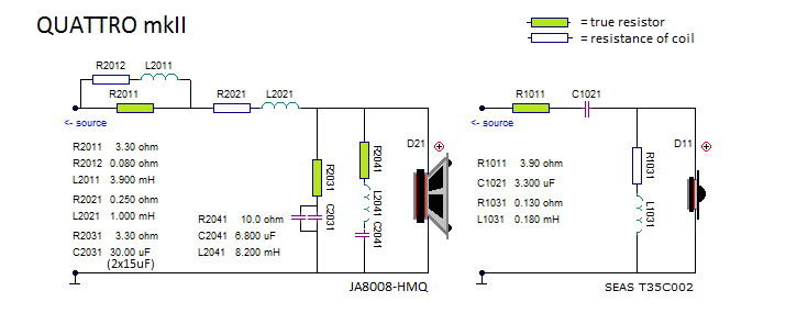
Crossover
Back
to top
Go to parts list
The tweeter's
simplistic crossover is basically an LR2 filter
at 2.5 kHz. Making a true LR4 filter was tried by adding a
second capacitor in series with the tweeter. This looks really nice in
paper but didn't sound as good as the simple LR2 filter.
Fine-tuning tweeter crossover was done
extensively with the help of a sampled and
multiplied sequence of
"Siri's
Killer Note". This proved extremely
useful and eventually gave a crossover that would
never have emerged from modelling alone.
Tweeter attenuation may be fine-tuned to personal
taste, your front gear and room acoustics. I
think 4R7 is suitable for most. If you want more treble, reduce
R1011 to 3R9. Also try 5R6 if you
find the treble too forward. My default is 5R6 to make a natural
blend of basic notes and overtones. 5R6 actually means treble
range above 5 kHz 1-1½ dB below average midrange
level. I've almost always found this voicing to
produce the most natural timbre.
Midwoofer crossover could be
simplified with the new JA8008-HMQ driver as the RC circuit
across L2021 could be omitted.
To
lower system sensitivity L2011 is bypassed by
R2011. Next we have the usual series coil, here
1.0 mH. R2031 and C2031 shapes the roll-off close to an LR4
profile, thus an overall asymmetrical crossover.
A lot of things were
tried to omit the midrange notch filter
(R2041+C2041+L2141) but this minor 1.5 dB bump at
600 Hz just proved too much in the long run. Not
having the notch filter on certain recordings
just made the 8008 driver say: Hey - look at me!
Some midrange, huh... Drivers should draw as
little attention as possible. Check measurement
page to see what it means. Link below.
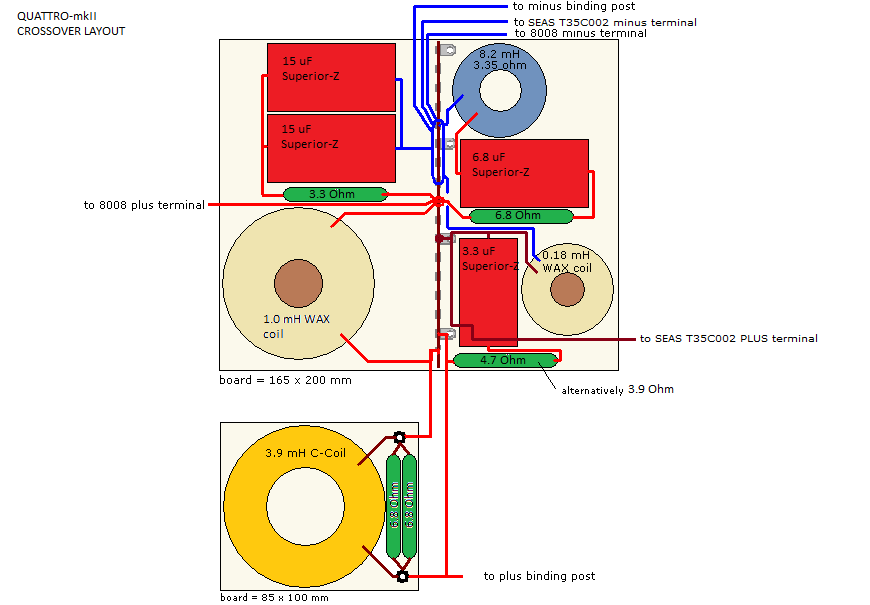
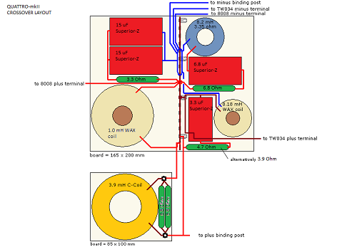
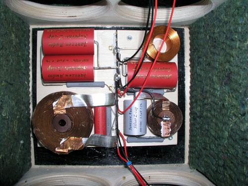
Crossover Layout
Click
image to view large.
Pay notice the new 15 uF Sup-Z caps are larger
than seen on drawing and needs to be stacked.
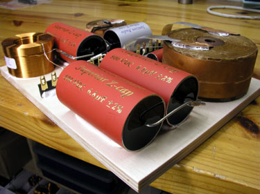 
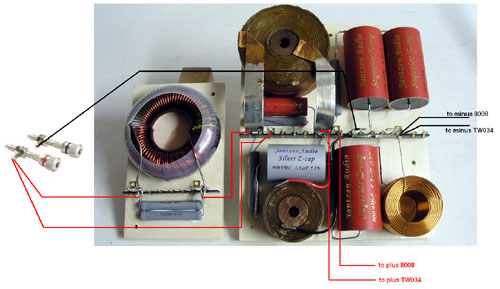
Wiring. Click image to view large.
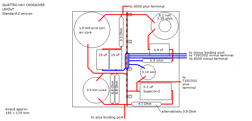
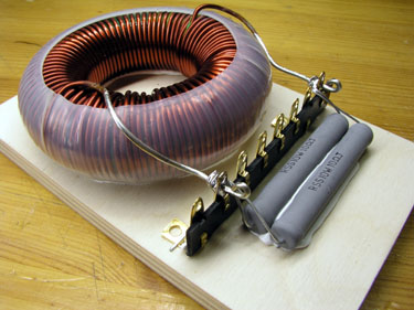
Crossover Layout
Standard-Z/Superior-Z
Version
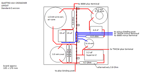
click image to view large
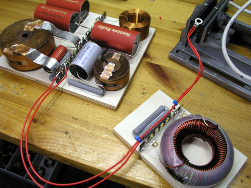  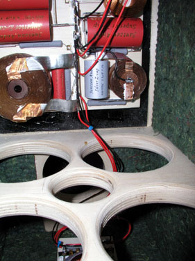
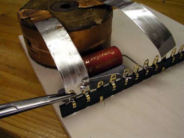
Left: Soldering wires to terminal tags. Middle: C-Coil at
bottom of cabinet, fastened with screws through felt
layer. Right: Both sections in place.
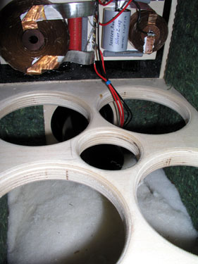  
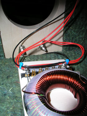
Left: Damping material covering C-coil at bottom. Middle:
Main board on rear panel fastened with screws. Right:
Damping material covering main board and side panels next
to 8008 driver.
Measurements
on finished speaker
Back
to top
A few comments on
MEASUREMENTS before you start interpreting all the readings below.
First of all, if we think measurements will
tell us how a speaker sounds, we're wrong. The perception of sound is
way too subjective to be reflected in any measurements we can perform. A
loudspeaker system is meant to give us a satisfying idea of an acoustic
event and for some people a pair of 5 USD ear-plugs are enough, others
spend 200 kUSD on a truly full-range pair of speakers - and the latter
may not be happier than the former.
Measurements may give us an idea
of tonal balance of a system, i.e. too much or too little energy in
certain areas. Measurements may tell us about bass extension if
far-field measurements are merged with near-field measurements. In
addition to this, ports may contribute to bass extension. Most of us
diy'ers do not have access to an anechoic room for full-range
measurements from 20-20000 Hz.
What cannot be seen is what kind of
bass performance we get in a given room. Bass performance is highly
dependent on in-room placement of your speaker and the same speaker can
be boomy in one place and lean in another. Actual SPL level at 1 meter
distance and 2.8V input is useful for en estimate of system sensitivity
and combined with the impedance profile may give an idea of how powerful
an amplifier is needed to drive the speaker to adequate levels.
What
measurements do not tell is the very sound of the speaker unless
displaying serious linear distortion. The level of transparency, the
ability to resolve micro-details, the "speed" of the bass, etc., cannot
be derived from these data. Distortion measurements rarely tell much
unless seriously bad, and most modern drivers display low distortion
within their specified operating range.
Many people put way too much
into these graphs and my comments here are only meant as warning against
over-interpretation. There are more to good sound than what can be
extracted from a few graphs. Every graph needs interpretation in terms
of what it means sonically and how it impacts our choice of mating
drivers, cabinet and crossover design.
What measurements certainly do
not tell is the sonic signature of the drivers, because cones made from
polyprop, alu, kevlar, paper, glass fiber, carbon fiber, magnesium,
ceramics or even diamonds all have their way of colouring the sound.
Left:
SPL at 1 meter, 2 8 volt. Overall system sensitivity = 90-91
dB/2.8V/1 m.
Right: Final system impedance. Minimum where is matters is 9.5 ohms at
40 Hz and ~7 ohms around 200 Hz.
My 20 watts Audio Mirror SET amps just love these
speakers!
Left: Impedance displaying 6.9 Ohm @ 180 Hz
(dotted line).
Right: SPL from drivers driven from crossover and summed response (red).
Point of crossover is around 2.3 kHz.
For those addicted to measurements, click here to view it all.
These are
the old measurements but as the new 8008-HMQ is tuned to the same
frequency response I shall not repeat all the measurement.
Cabinet
construction pics
Generally:
Never route for ports and drivers before at hand! Nor
drill holes for terminals before at hand.
Do
your own measurements and make test routings before doing
the actual cabinets. With Baltic birch there's no room
for errors.
Last but not least: Below is an attempt to
make a nice Baltic birch solution. Baltic birch is not a
particularly easy material for cabinet construction and
the
front panels take solid maple and mahogany fillets, not
something that can be made without access to a decent
table saw. Obviously the same cabs can
be made from 8 sheets/cabinet of MDF - and the sonic
results will most likely be the same. Choice is yours.
Happy building!
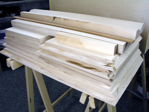 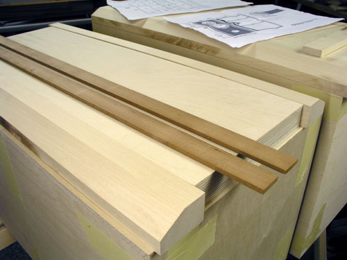
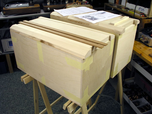
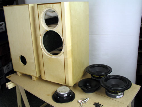
Left:
All parts for one speaker. Right: Test assembly with
painter's tape. Mahogany fillets for front panel.
Left:
Checking rear panel fit before gluing.
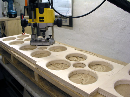 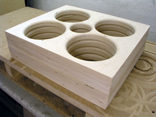
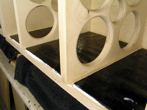
Routing
the brace panels. Quite some holes, but with a 6 mm
router bit Baltic birch is easy. I rounded the edges
because it looks nice.
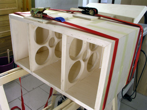 
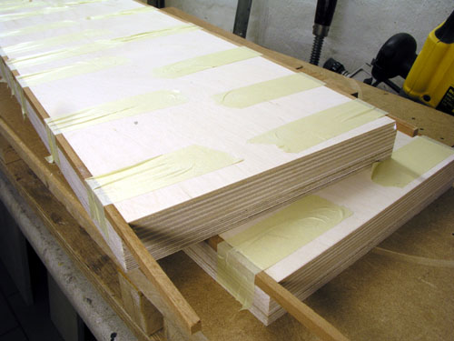
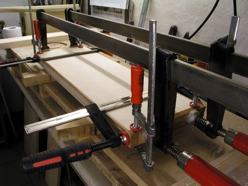
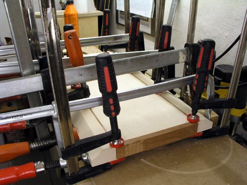
Left:
Gluing the first cabinet. Only painter's tape and two
straps are used. Measure front diagonal to make sure it's
truly rectangular!
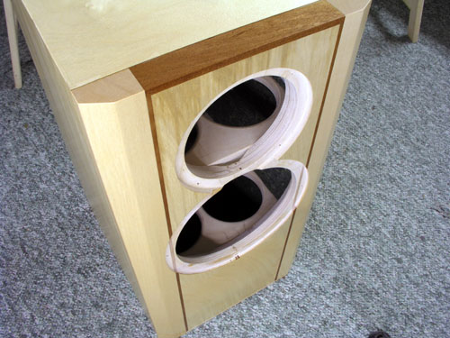
Right: Placement of port and terminals.
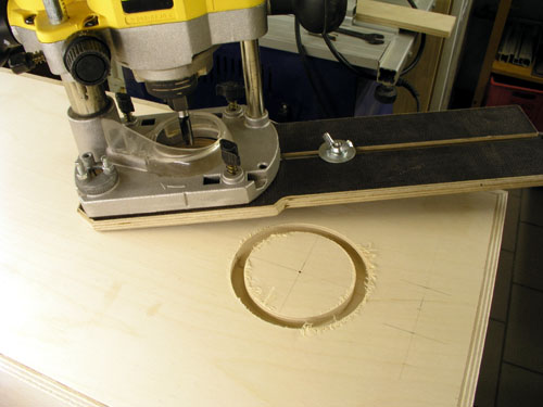 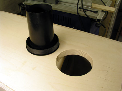
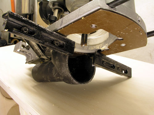
Routing for the port. Diameter = 96.5 mm. Make a hole
having a diameter approx. 0.2 mm less than measured
diameter of port base so that
you have to squeeze in the port and it stays firm - and
can be removed again for preferred port tuning.
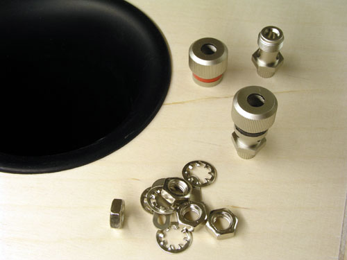 
Left: Drilling holes for terminals (7 mm). Right: Gluing
front panel vertical fillets. Only tape is used.
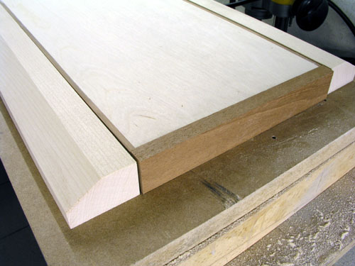 
Left: Checking top and bottom front panel fillets before
gluing. Right: Gluing the same.
 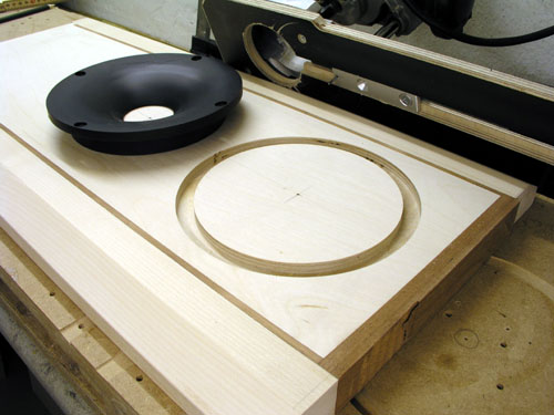
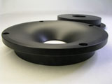
Left: Gluing front panel side fillets. Right: Routing for
the waveguide. When routing for the 8008 driver, the
waveguide must be in place.
Routing finished. Final thing I do is cutting length of
front panel on a table saw.
Front panel side fillets have been trimmed by routing,
keeping the front in place by two clamps.
This I do before routing for drivers to have a place
surface for the router. Sliding over holes is not a good
idea.
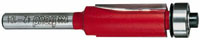
Trimmer router bit.
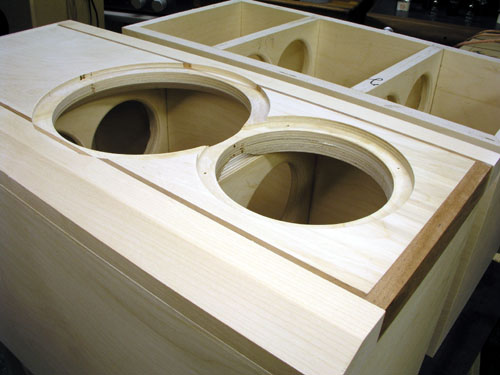
Do not forget to chamfer JA8008
driver hole on rear side. 45 deg. at ~15 mm depth.
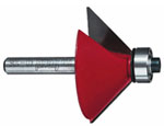
Router bit used for chamfering.
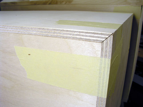
Before gluing the front panel:
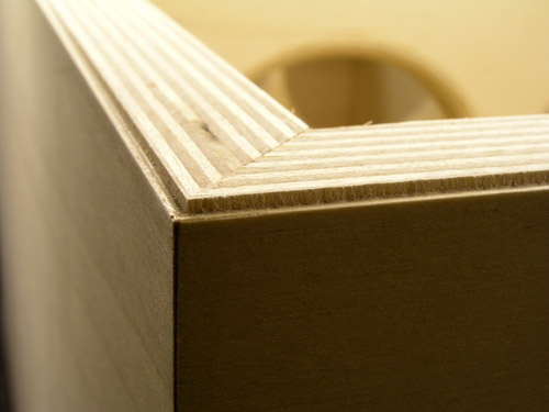
Gluing a front panel to the cabinet will never be 100%
perfect, thus before gluing the front panel to the
cabinet I always make a small groove, 1.5 x 1.5 mm, on
cabinet front edges.
This is also a way of handling the real drawback of
Baltic birch: Ripped edges. The outer veneer of Baltic
birch is rather soft and either sawing or routing will
often lead to a ripped edge.
Left: Router with guide. Right: Smooth the groove with
some grade ~400 sandpaper and start sanding the opposite
way of routing not to rip edges.
Bitumen damping pads
First of all: Bitumen pads damp panel
resonances. It does not absorb sound at all. (I have this
question regularly).
Adding the first 4 mm bitumen layers. Although the
bitumen pads I use are self-adhesive,
I use an adhesive meant for floor vinyl, having flexible
properties - and presumably adds to damping properties.
Self-adhesive pads like these heavy 4 mm sheets tend to
fall off over time if not glued.
Bitumen pads used for damping panel vibration.
In total 1 m^2 bitumen pads is needed.
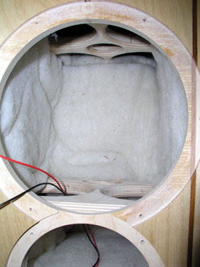
Cabinet damping
Two materials are used for cabinet damping: 8 mm felt and
30 mm acoustilus (supplied with the kit).
8 mm FELT
 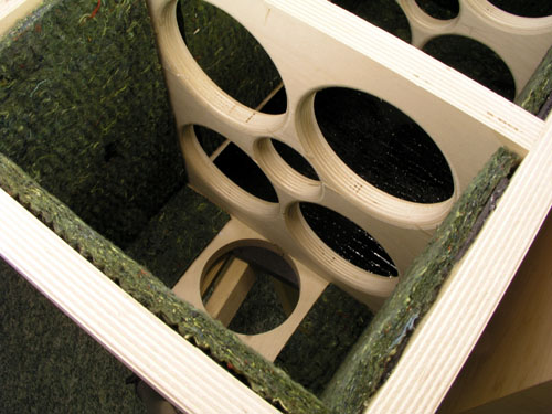
Felt on all internal panels except front panel, that is:
On front panel in front of the vent I added felt too plus a layer of
acoustilux.
For keeping the felt in place I used Pattex
"no-more-nails" glue. Three strips of glue/felt
sheet.
Acoustilux

FINALLY -
Finally! Sanded, lacquered, ready for mounting of
drivers, ports, terminals, etc.
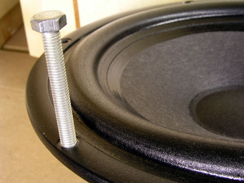 
Left: Cheap trick: If your routings are tight, you may
have trouble removing drivers for changing damping
materials, crossover tweaking, etc.
Chassis holes are Ø 5 mm, make 6 mm threads in two
opposite holes! Makes life a lot easier when removing the
driver :-)
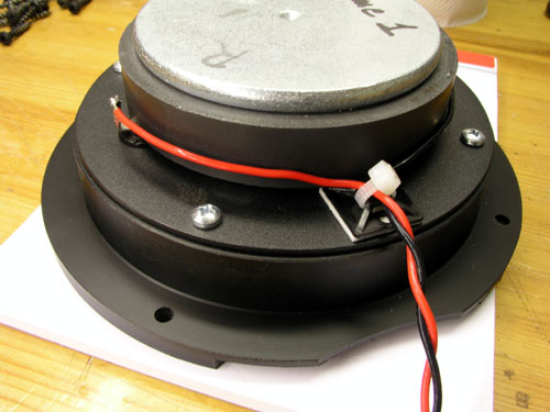 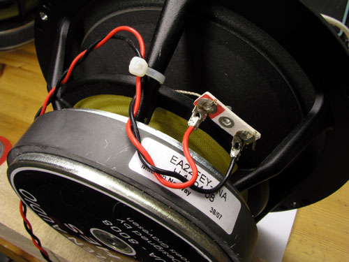
Secure leads from drivers like seen on photos. Ripped
terminals are a real pain! Wires used are silver plated
copper in teflon.
Read here how you fasten
the waveguide to the tweeter.
Parts
list
Back
to top
back to
schematics

Above the parts list for the all-Superior-Z
cap version.
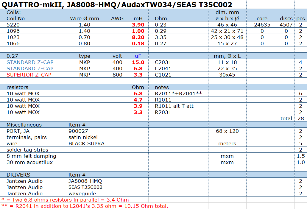
Above the parts list for the
Superior-Z/Standard-Z cap version.
Complete kit only
available from Jantzen Audio:
contact@jantzen-audio.com
Contact Jantzen Audio for shipping
details - please state where you live to calculate shipping
cost.
All kit and component prices may
be subject to change and are always to be confirmed by Jantzen Audio
Denmark.
All technical questions at
troels.gravesen@hotmail.com
Download
all Kit
Sales Presentations:

Back
to top
|