ScanSpeak
Revelator-51
Copyright 2023 © Troels Gravesen
Go to on this page:
DRIVERS
CROSSOVER
CABINET
WORKSHOP PICS
MEASUREMENTS
SPEAKER-KIT
CROSSOVER LAYOUT
Time for an update on my old
Revelator-4R construction. New tweeter, new and simpler crossover,
time-aligned drivers, etc. The Revelator-4R will be discontinued from
Jantzen Audio, but should you still prefer the ring-radiator and 4th
order crossover, you can buy the schematics directly from me.
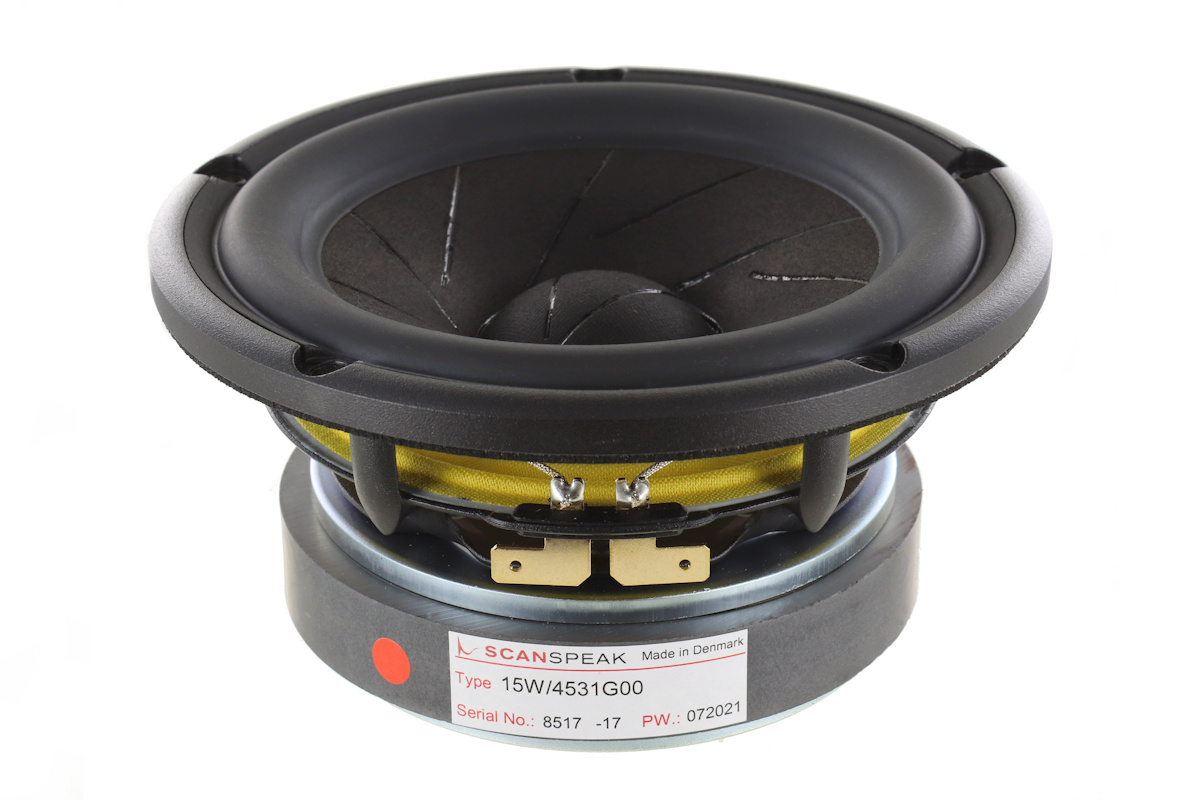
The mid-bass stays the same being the foundation of the construction, and
this magnificent drivers is the same as 10 years ago. If it works -
don't change it!
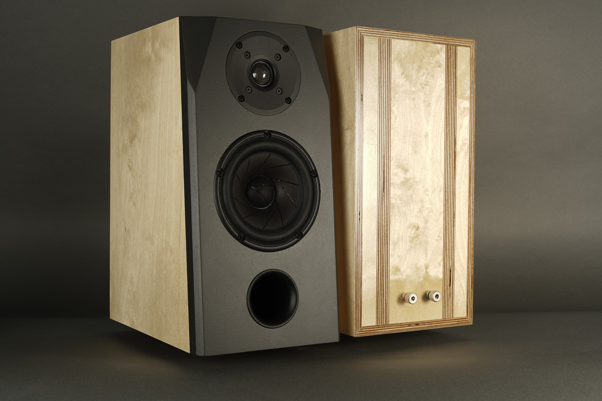
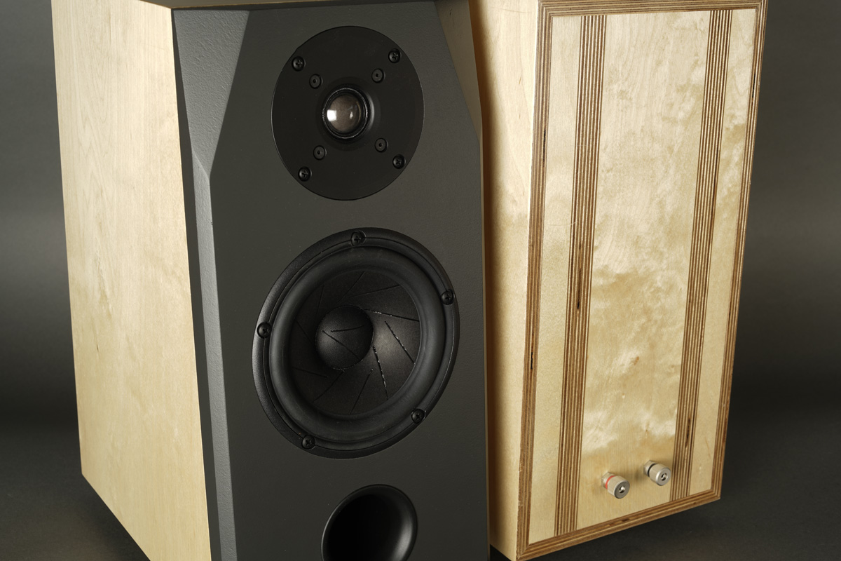
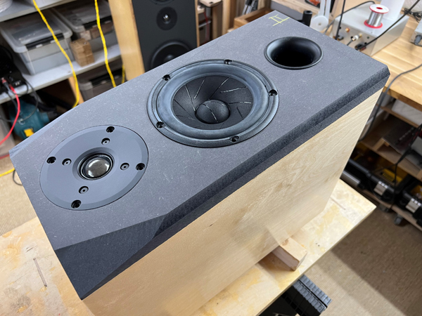
To time-align drivers I chose a sloped front panel - easier than a
stepped front panel, and I know kit customers appreciate simple.
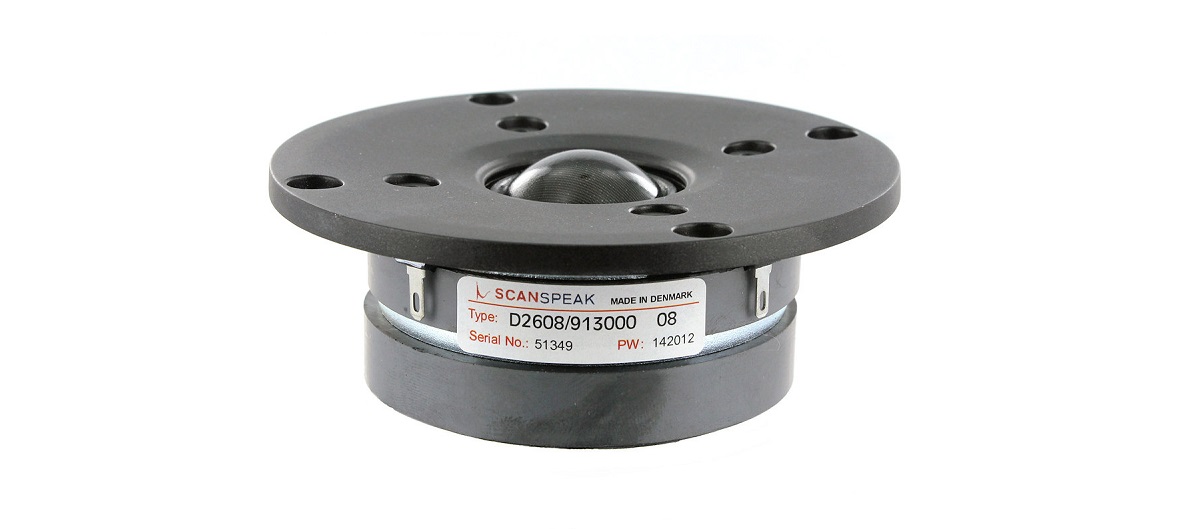
For many constructions in the not-so-expensive range of speakers, I have
used the venerable D2608/913000. Still the best affordable tweeter
I know of.
Crossover is a simple LR2 filter crossed at ~2 kHz and by few means the drivers can manage a smooth roll-off on both flanks and due to the sloped front panel, good phase integration can be achieved.
The 15W basket is actually some 148 mm diameter. 148 mm equals 5.8", thus actually
close to a 6"
driver in old terms. Now, I used to think of the 15W as a 5" driver but
connecting my EAR-861 amp, this driver really acts as a 6" driver,
delivering decent bass, ultra transparent midrange at the crossover
makes a seamless transition of the treble range. I couldn't be more
pleased from this update.
30 watts is more than needed to make this speaker sing in a not too
large room.
Basics:
2-driver speaker.
Dimensions: 20 x 30 x 40 cm, WxDxH.
System sensitivity: 86 dB/2.8V/1 meter.
Impedance: 4-8 Ohms.
Power requirement: 20+ watts/channel.
Useful links (Please
follow all links before e-mailing!):
http://www.troelsgravesen.dk/tips.htm
http://www.troelsgravesen.dk/tips.htm#CONSTRUCTION_OF_CROSSOVERS
http://www.troelsgravesen.dk/crossovers.htm
http://www.troelsgravesen.dk/LCR-RC.htm
http://www.troelsgravesen.dk/Inverted-Polarity.htm
http://www.troelsgravesen.dk/choices.htm
http://www.troelsgravesen.dk/power-handling.htm
Download specs here:
D2608/913000
15W/4531G00
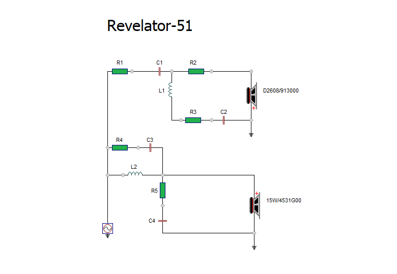
The crossover features a simple LR2 filter with a crossover point around
2300 Hz.
Go to crossover layout.
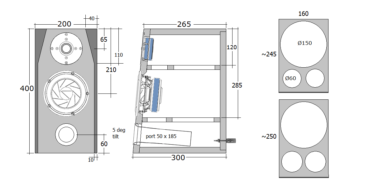
Cabinets were made from 20 mm Baltic birch and for the front panel I
chose 25 mm black MDF (really HDF, read
here). The slight chamfering of front panel round
the tweeter is optional. I does make a slight difference in frequency
response, but nothing that takes changes to the crossover.
The port is 50 x 185 mm (full length) making a port tuning around 38 Hz.
F3 ~42 Hz, quite decent from such small speaker.
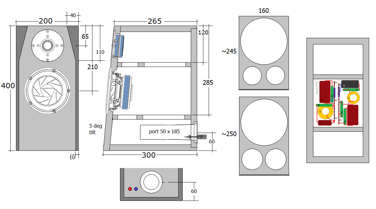
The reason for showing two options is that whenever I launch a
construction with the port to the front or back, I immediately have a
mail if the port can be opposite. Oh yes, take your pick! With the port
to the rear, place terminals to one side.
And I did not try the rear ported version to find out which is best.
Ports often leak some midrange - and not the best part. But I didn't
notice any midrange disturbance from my front ported cabinets.
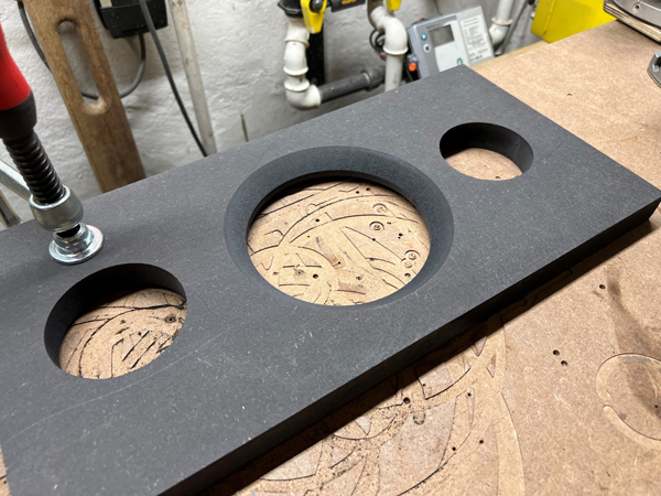
Faceting of front panel is optional as it does very little to the
frequency response, but I think it looks nice.
However, easy done if you have a table saw. Set cutting angle to 27 deg.
Set sliding table angle to 10 deg. and cut to a depth of ~20 mm - that
is, if you use a 25 mm front panel as I did.
Faceting can be done by hand,
chisel and sandpaper.
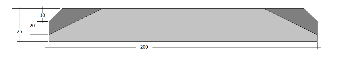
My front panels seen from top.
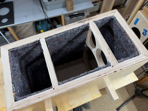
Simple cabinet, so there won't be a whole lot of workshop images.
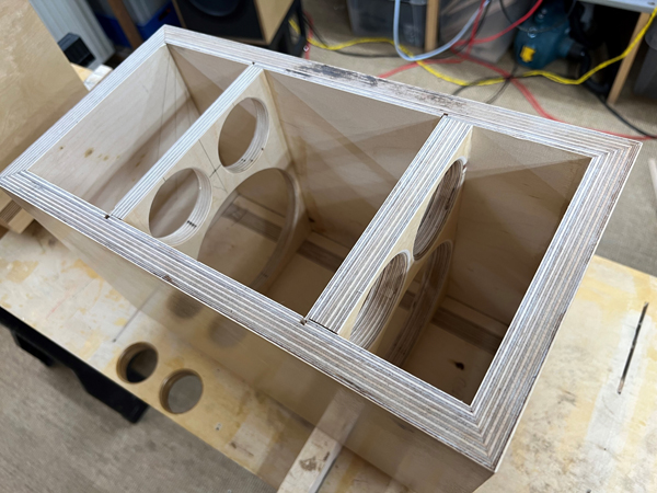
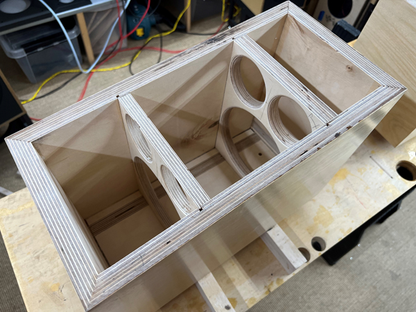
Cabs with braces. Ready for felt damping.
Add felt to all internal panels except rear middle, where the crossover
goes.
You may also leave a bare spot at bottom where the port goes.
Chamfer midbass driver hole to allow
free ventilation.
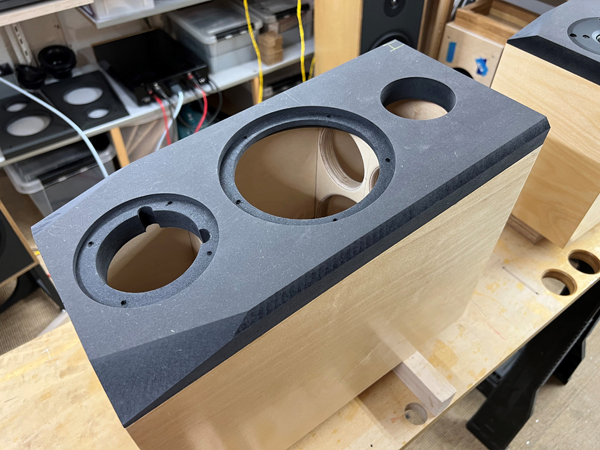
Testing front panel and driver rebates.
The tweeter rebate depth was 4.3 mm and 15W rebate depth 6.5 mm.
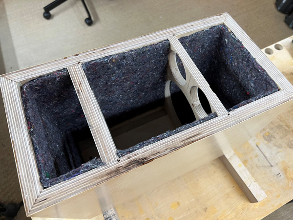
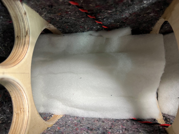
All felt pads in place.
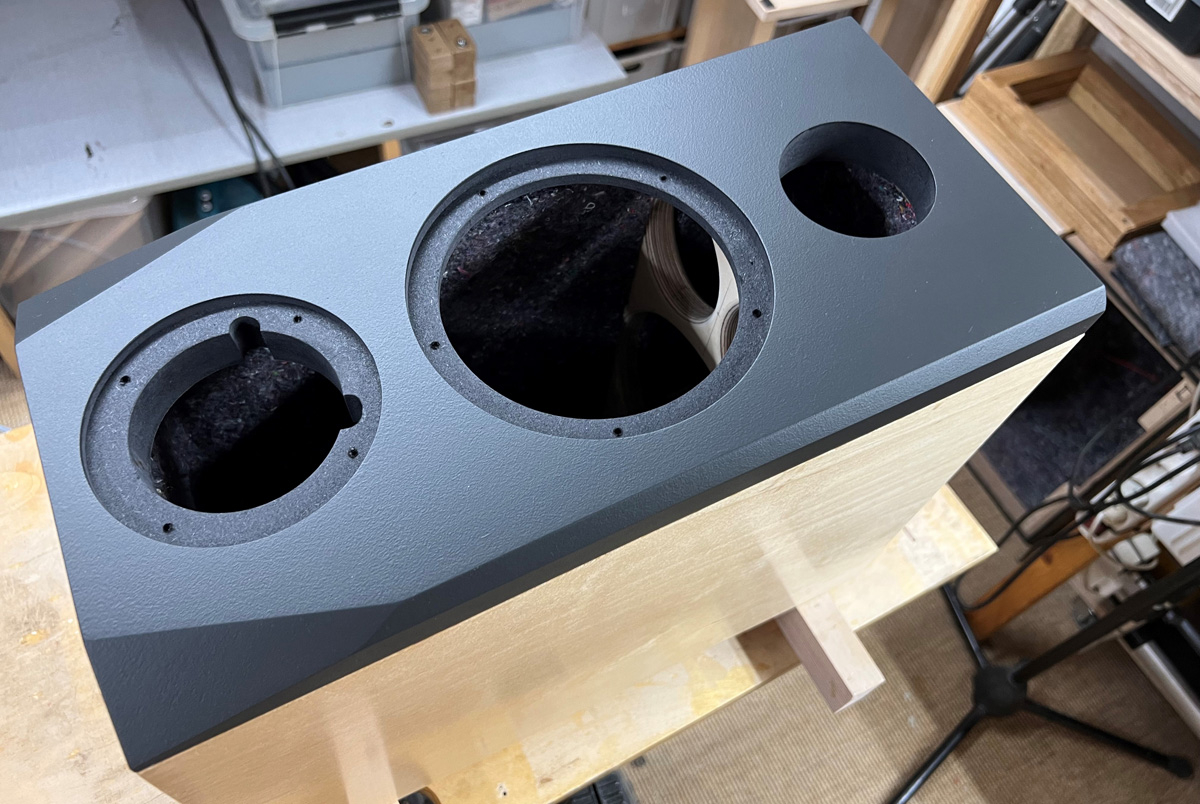
Front panels painted and ready for mounting.
A few comments on
MEASUREMENTS before you start interpreting the readings below.
First of all, if we think measurements will
tell us how a speaker sounds, we're wrong. The perception of sound is
way too subjective to be reflected in any measurements we can perform. A
loudspeaker system is meant to give us a satisfying idea of an acoustic
event and for some people a pair of 5 USD ear-plugs are enough, others
spend 200 kUSD on a truly full-range pair of speakers - and the latter
may not be happier than the former.
Measurements may give us an idea of tonal balance of a system, i.e. too
much or too little energy in certain areas, although dispersion
characteristics play a vital role here. A two-way 7+1 and a three-way
7+4+1 may display similar horizontal dispersion, yet sound very
different. Measurements may tell us about bass extension if far-field
measurements are merged with near-field measurements. In addition to
this, ports may contribute to bass extension. Most of we diy'ers do not
have access to an anechoic room for full-range measurements from
20-20000 Hz.
What cannot be seen is what kind of bass performance we get in a given
room. Bass performance is highly dependent on in-room placement of your
speaker and the same speaker can be boomy in one place and lean in
another. Actual SPL level at 1 meter distance and 2.8V input is useful
for en estimate of system sensitivity and combined with the impedance
profile may give an idea of how powerful an amplifier is needed to drive
the speaker to adequate levels.
What measurements do not tell is the very sound of the speaker unless
displaying serious linear distortion. The level of transparency, the
ability to resolve micro-details, the "speed" of the bass, etc., cannot
be derived from these data. Distortion measurements rarely tell much
unless seriously bad, and most modern drivers display low distortion
within their specified operating range.
Many people put way too much into these graphs and my comments here are
only meant as warning against over-interpretation. There are more to
good sound than what can be extracted from a few graphs. Every graph
needs interpretation in terms of what it means sonically and how it
impacts our choice of mating drivers, cabinet and crossover design.
What measurements certainly do not tell is the sonic signature of the
speaker, because speaker cones made from polypropylene, aluminum,
Kevlar, paper, glass fiber, carbon fiber, magnesium, ceramics or even
diamonds all have their way of adding spices to the stew. Nor do
measurements tell what impact the quality of the crossover components
add to the sound, from state of the art components to the cheapest of
coils and caps, they all measure the same if values are correct, yet
sound very different.
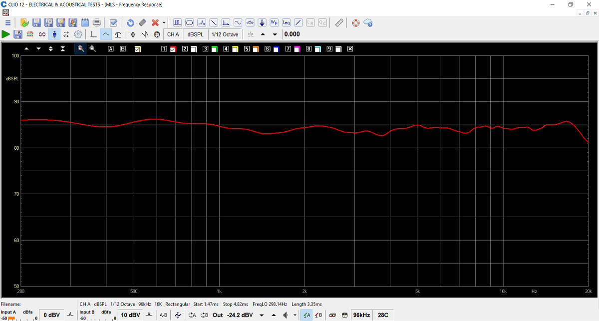
Frequency response of finished speaker.
System sensitivity around 86 dB/2.8V/1 meter.
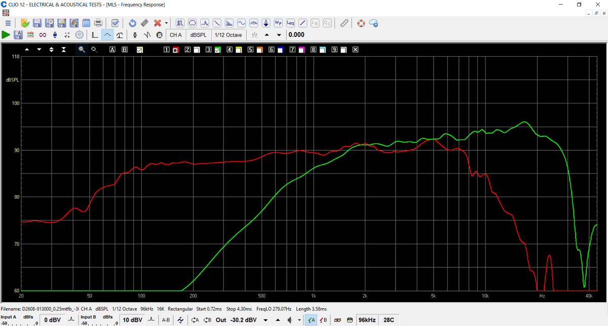
Frequency response of individual drivers. I'd
forgotten how easy the 15W is...
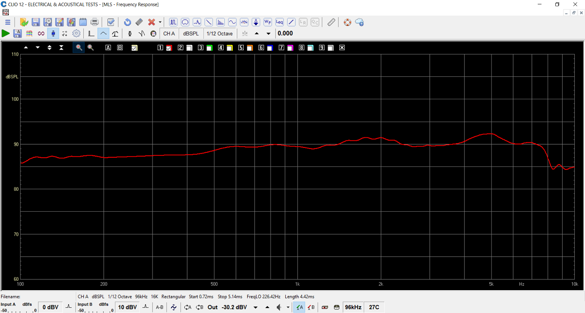
Here the 15W alone from 100-10000 Hz, the
range that matters. What's not to like?
Merged with nearfield response @ 200 Hz.
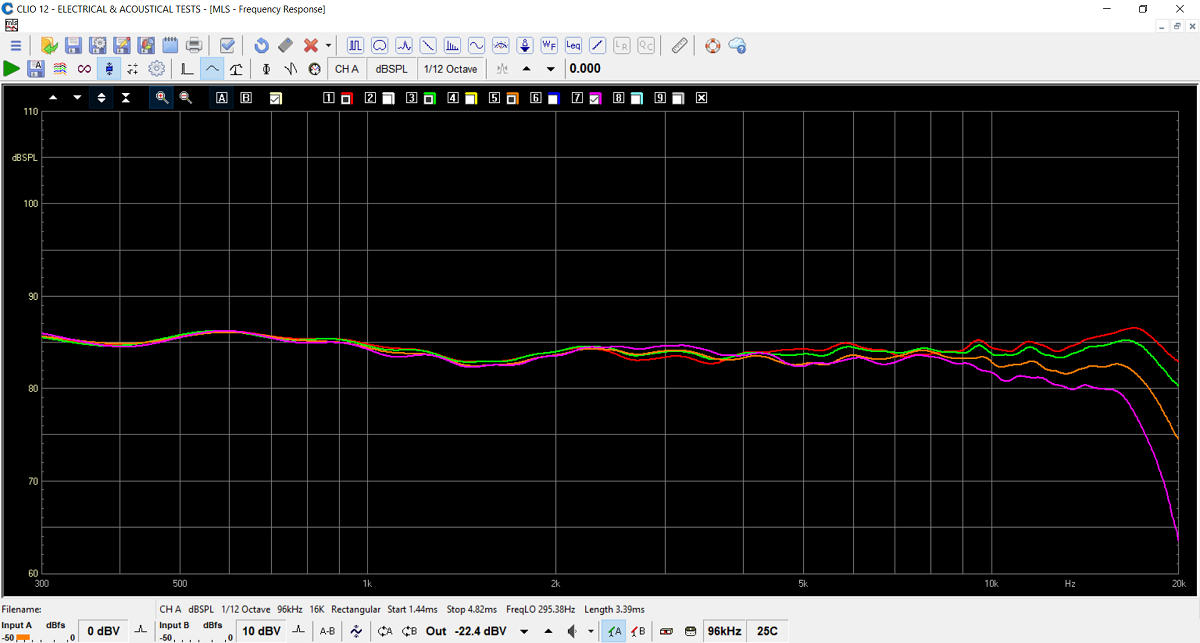
Horizontal dispersion at 0, 10, 20 and 30
deg. off-axis.
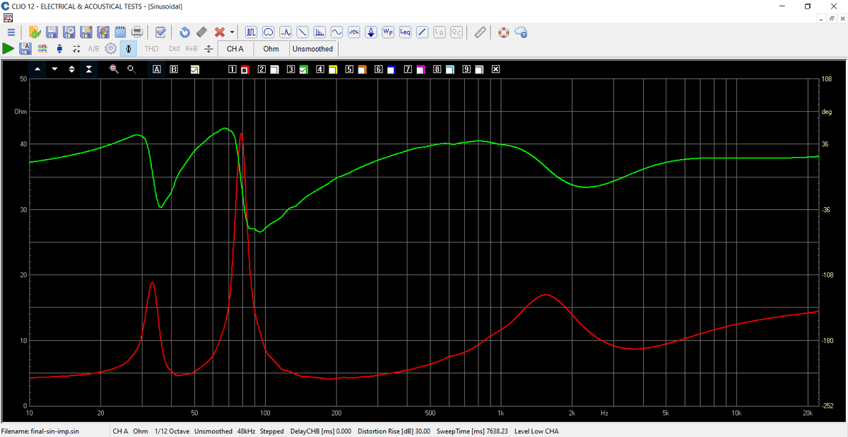
Final system impedance. Minimum 4 Ohms.
Port-tuning around 43 Hz.
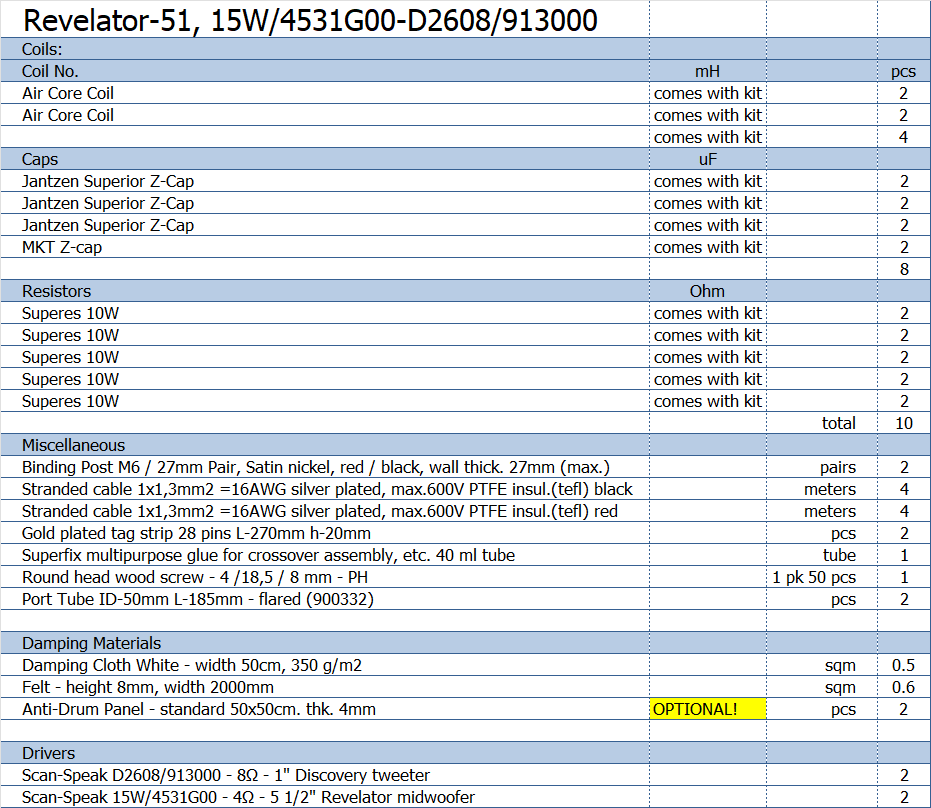
All kit and component prices may be subject to change and are always to be confirmed by Jantzen Audio Denmark.
Kits can always be bought with/without drivers, or some of the drivers.
Download Complete Kit Sale Presentations:

All technical questions to troels.gravesen@hotmail.com
All questions regarding purchase of kits, please mail Jantzen Audio at contact@jantzen-audio.com
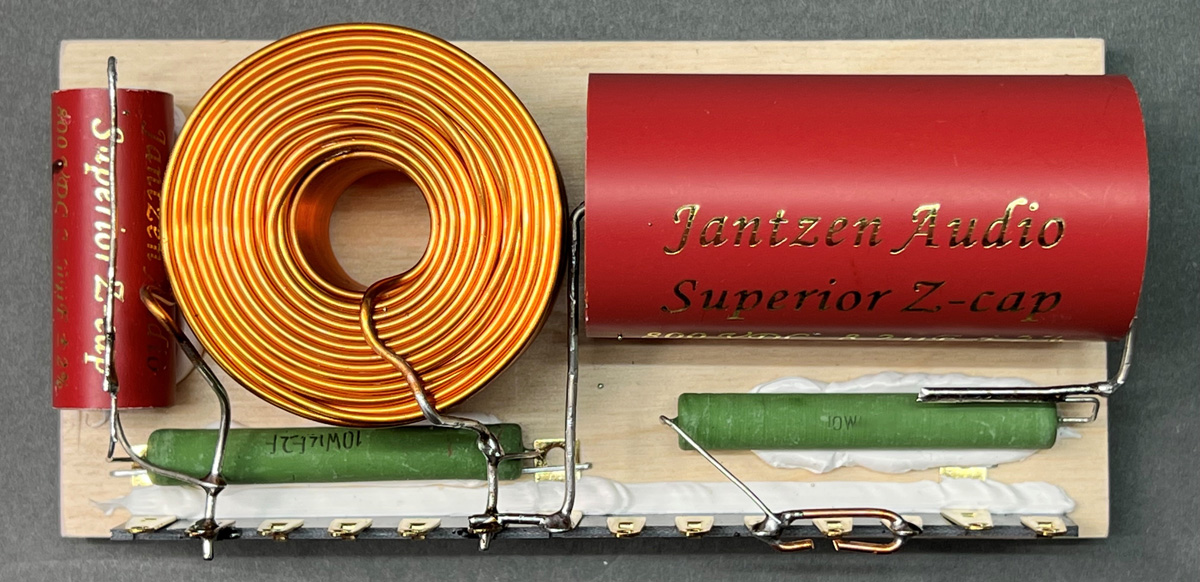
CROSSOVER-LAYOUT
BACK TO INDEX
Check this out before start making crossovers:
http://www.troelsgravesen.dk/tips.htm#CONSTRUCTION_OF_CROSSOVERS
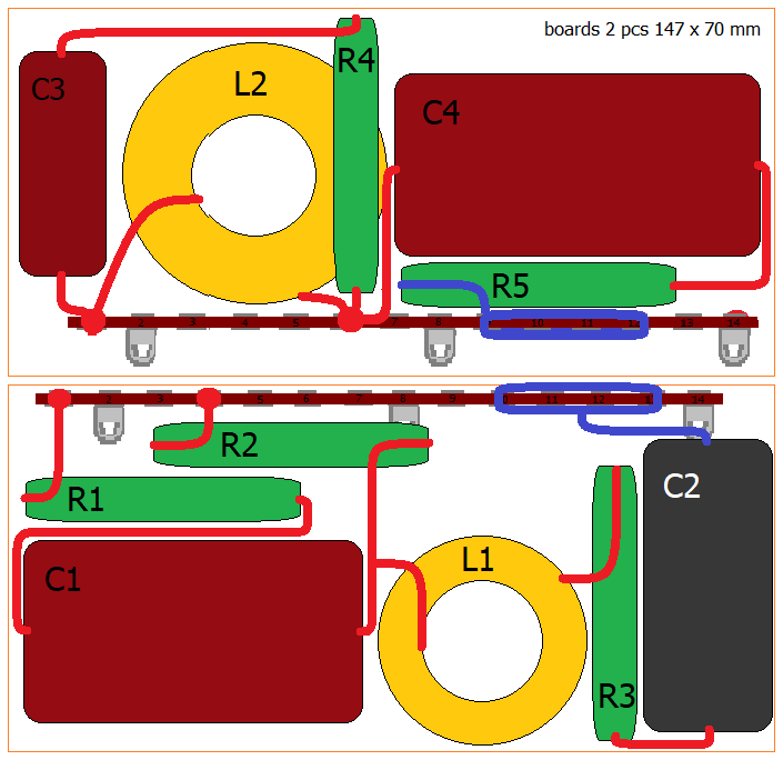
The reason for two boards is simple: You have to get it through the 15M
driver hole!
Small speakers always pose the problem of getting the crossover in
place.
Tweeter layout.
Bass layout.
By reversing the solder tag strip R4 could be placed on the board.
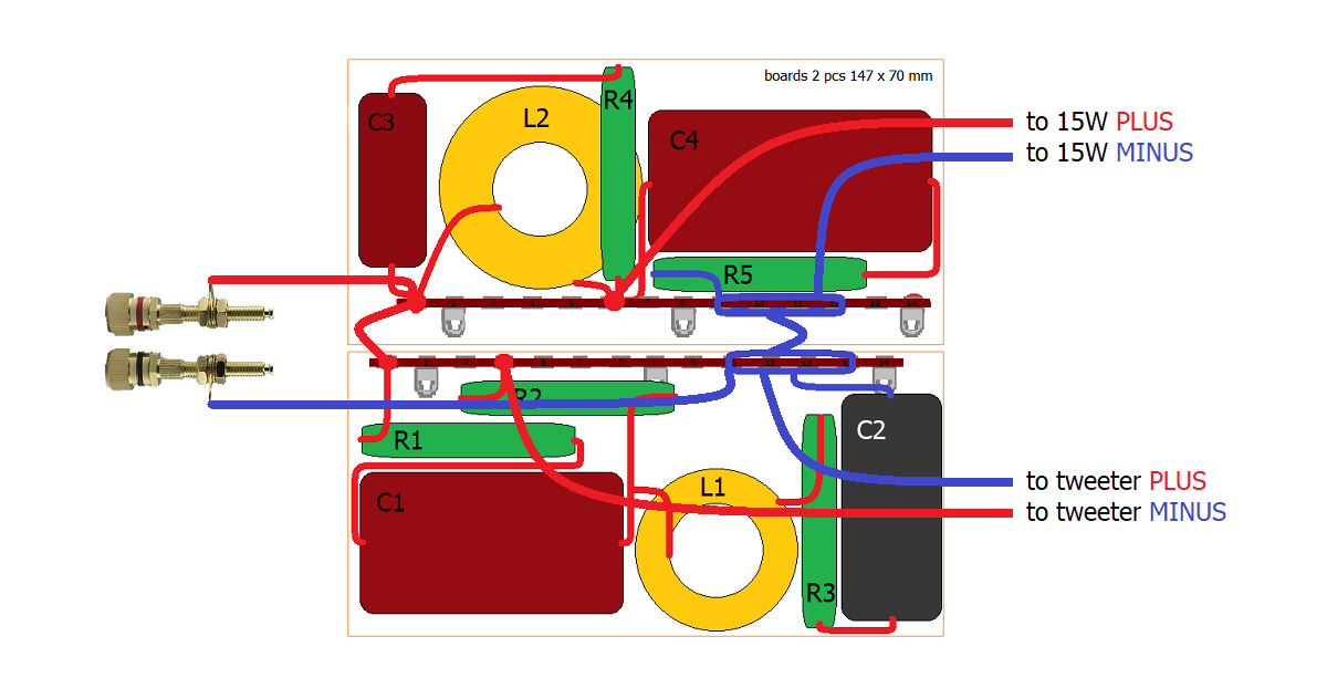
Make a PLUS/MINUS loop from one board to the other.
Note tweeter with inverted polarity!!
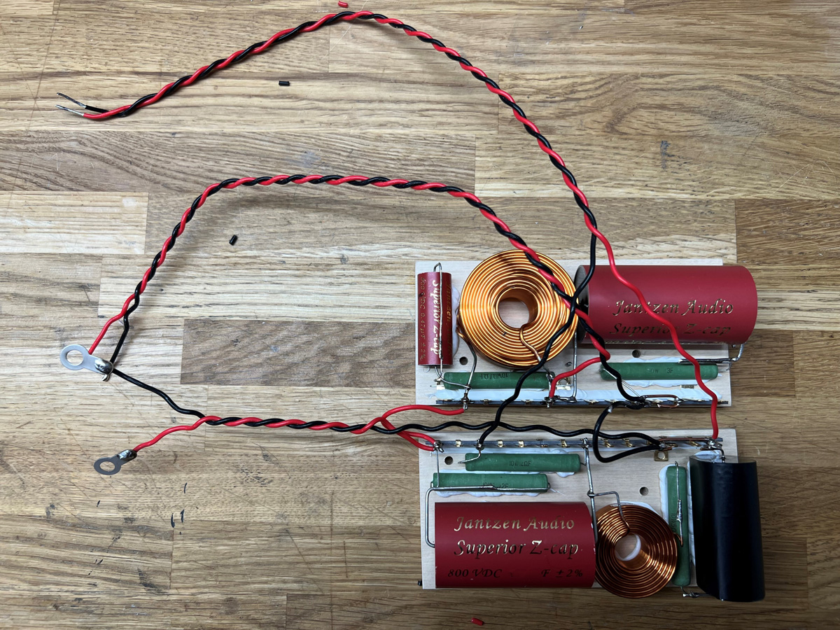
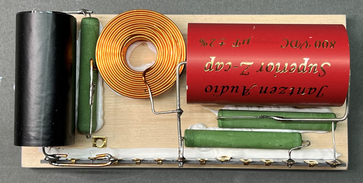
Crossover wired up and ready for mounting.
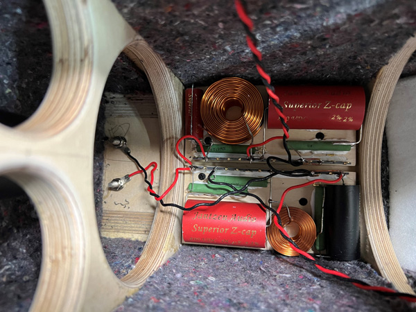
Crossovers mounted on rear panel and attached to terminals. Use two
screws per board.
Cover with a folded 15x50 cm piece of acoustilux.