DIY Loudspeakers: HOME  INDEX  UPDATES  RESPONSE  WHAT'S NEW


SEAS CURV
Copyright 2012-21©TroelsGravesen

DRIVERS     CROSSOVER     CABINET     SPEAKER KIT     MEASUREMENTS     CROSSOVER LAYOUT   CROSSOVER WIRING


Click images to view large

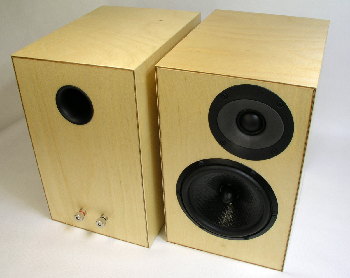
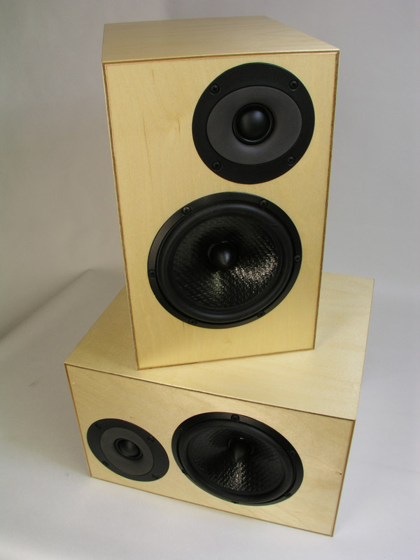
Spending more than a year on Jenzen speakers, handling a small 8 liter speaker is quite a relief. Only real challenge is placing the crossover in the small rear 
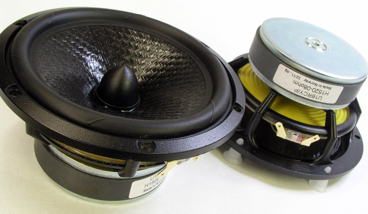
compartment, but more on this later. Ever since the launch of the CURV cone material, reviewed in Voice Coil, October 2006, I'd wanted to try out a drivers made with this cone material. I always liked the sound of the SEAS TPX cone drivers, unfortunately discontinued. I still have 
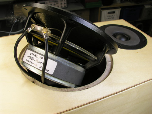
four T17RE drivers on the shelf with this cone material. 
Polypropylene, PP, has excellent properties for speaker cones, in particular mineral filled PP used by e.g. Dynaudio and AudioTechnology for decades. A fairly new variant of PP is the CURV® material being a "woven, self-reinforced polypropylene material with excellent internal damping" to quote SEAS' introduction allowing low-loss rubber surrounds. CURV is more rigid compared to mineral filled PP, yet provides an exemplary roll-off profile as can be seen from measurements below.
And finally we have a 95 cm2 cm cone area from a SEAS 5" unit. Size matters and going from 75 cm2 to 95 cm2 does make a difference in mini-monitors. To my mind the U16RCY/P could well be placed in the EXCEL range of drivers - maybe with a copper phase plug and magnet rubber boot to fit the general appearance, although these features have nothing to do with sound quality.
The 29TFF/W tweeter provides an unusual flat frequency response and is an excellent partner for the CURV driver. Overall the performance of these drivers allow high quality reproduction from modest priced drivers.
The construction here features simplest possible cabinet work, something that should enable the first-timer to engage and build a pair of high-quality minis for a modest investment.

I can't help thinking of the old Vifa P13WH driver, which must have been produced in the tens of thousands, cherished by the DIY community and professionals. The P13WH was an easy driver allowing simple crossovers and should I point to a possible substitute, this SEAS driver is one of the candidates. Do not read this as a "replacement" candidate. Every new driver will require it's own fine-tuned crossover to render proper amplitude and phase. What this CURV driver can deliver compared to the old P13 is enhanced resolution, more micro-detail, a modern well-ventilated basket, higher mechanical Q and a light-weight foamed rubber surround - just to name a few features.

Useful links (Please read before writing!):
http://www.troelsgravesen.dk/tips.htm
http://www.troelsgravesen.dk/crossovers.htm
http://www.troelsgravesen.dk/LCR-RC.htm

FAQ (Please read before writing!):
You cannot change cabinet front panel dimensions and drivers' placement without needing a new crossover - and I cannot help.
You cannot use any other drivers with the crossover shown here.
Please read these files before e-maling:
http://www.troelsgravesen.dk/crossovers.htm
http://www.troelsgravesen.dk/choices.htm


Drivers
back to top

        
SEAS drivers H1520-08, U16RCY/P and H1318-06, 29TFF/W. Click links to view SEAS data files. Click images to view large.


Crossover
back to top

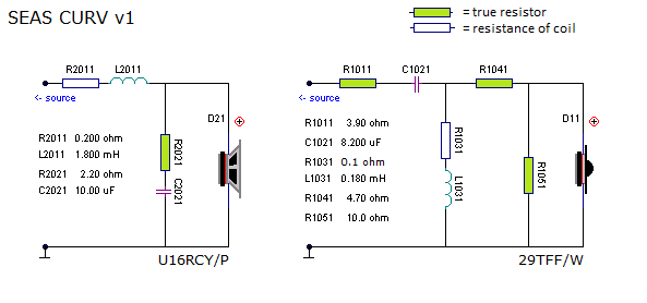
THE TOO OFTEN SEEN CROSSOVER SCHEMATICS


Above the quick'n dirty crossover.

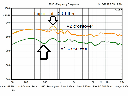
What is seen much too often is the crossover depicted above. Any driver mounted on a baffle will have an f3 = 11,600/width of baffle in cm, here 11,600/19 = 610 Hz, in short, we have a rising frequency response towards higher frequences and this is usually dealt with by adding a large series inductor for the midbass in order to tame too much energy around 1 kHz. Problem is that by doing so we tilt the response so much we have a dip right in the middle of the midrange around 500 Hz, see figure below (green hraph). Depending on the intrinsic response of the actual driver this may be more or less severe and a few times we can get away with the simple "v1" crossover. In this case we can't. With the Jenzen D as reference, it was immediately clear that there was something wrong with male vocals becoming thin and anemic. Thus, crossover v2 was produced  with a smaller coil in series with the midbass and a very narrow working equalising circuit consisting of R2031, L2031 and C2031. Orange and beige colour below. Now things started working out right and the speaker had a smooth presence and singers no longer sounded as had they gone half a meter back from the microphone.   


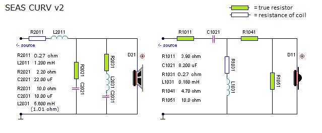
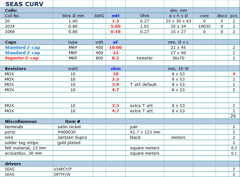
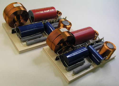
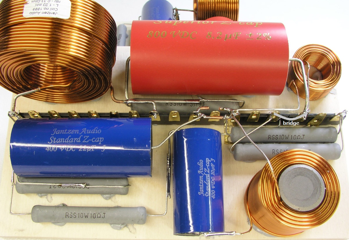
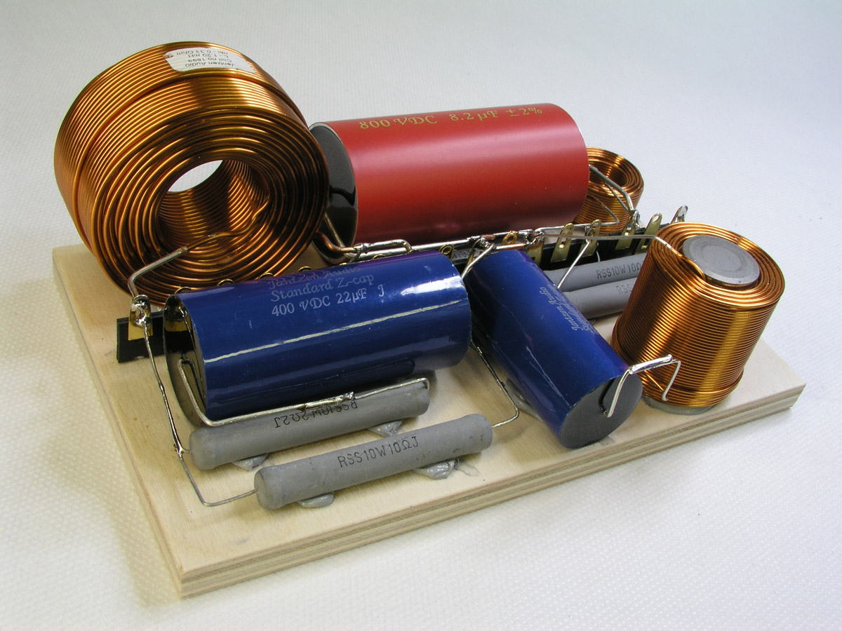
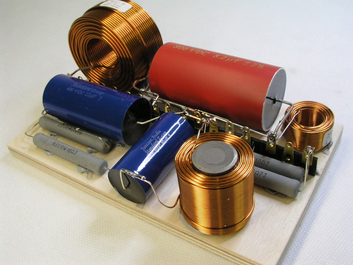
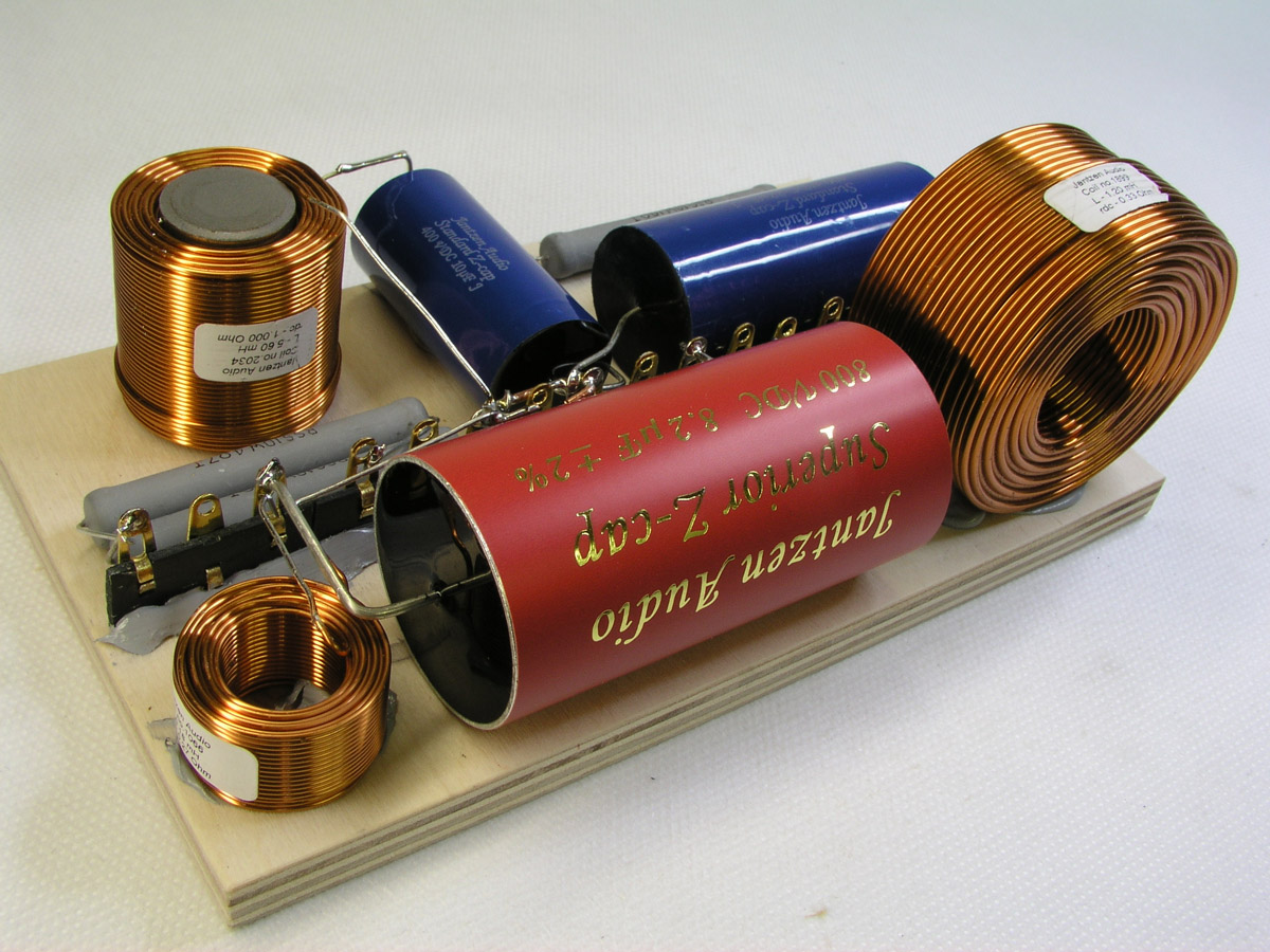
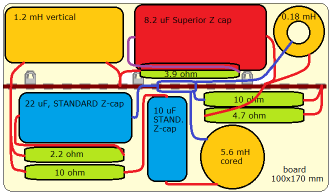
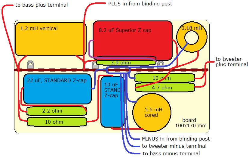
SEAS CURV FINAL CROSSOVER


Final SEAS CURV crossover. Please note the orientation of components in parallel LCR or CR circuit does not matter. My layout below may be different from what's seen here.

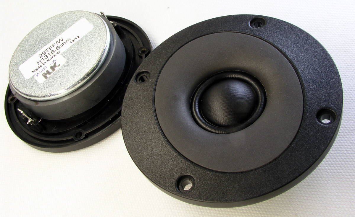
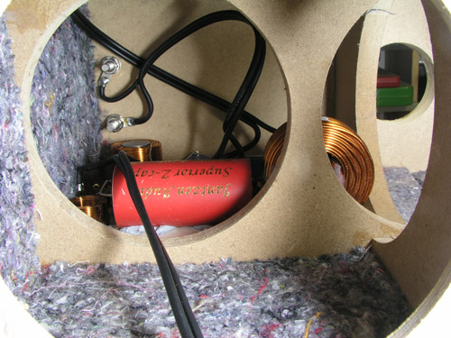
Rather unexpectedly a simple 2nd order filter (4th order acoustically) could be realised with the drivers both connected with positive polarity. Not too often this happens but it tells we can never predict the outcome of a crossover design before you have the drivers on the actual baffle and have done the measurements. The 29TFF/W does indeed have an unusual flat response making crossover work easy. Point of crossover is 2.2 kHz. As we only have a single capacitor in the tweeter circuit, I've picked a Superior Z-cap here not adding significantly to the overall cost. If budget is low you may replace this by a STANDARD Z-cap. Also the 500 grams air-cored coil for the midbass can be replaced by a cheaper cored inductor. If money allows, I wouldn't hesitate to use Superior Z-caps in all places, these drivers will deliver further detail if we use the best.


Cabinet
back to top


7-9 liter net volume is adequate for the U16RCY/P driver, here modeled for 8.5 liter providing F3 = 58 Hz.
With Fb = 48 Hz we get a little extra level below 100 Hz to compensate limited bass extension. 


Cabinet volume = 9 litres minus bracing, port and crossover, approx. 8.5 litres.
Place port on rear panel behind tweeter.
I didn't make the bracing exactly like seen on drawings but do make the lower hole in the vertical brace some 110 mm diameter to allow mounting of crossover.


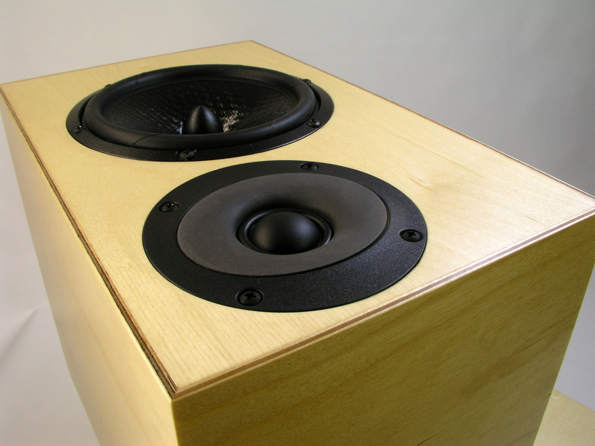
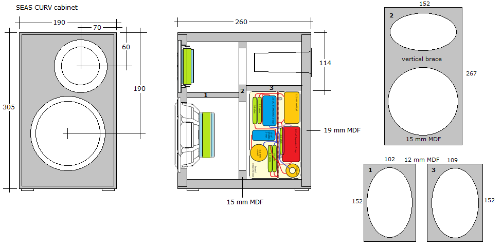
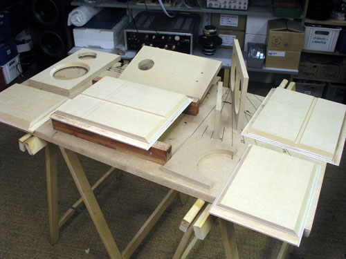
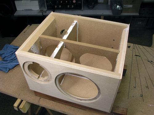
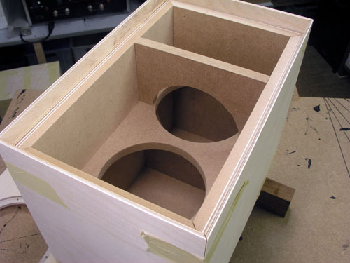
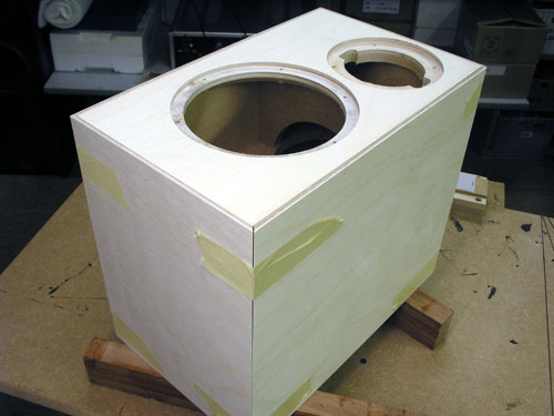
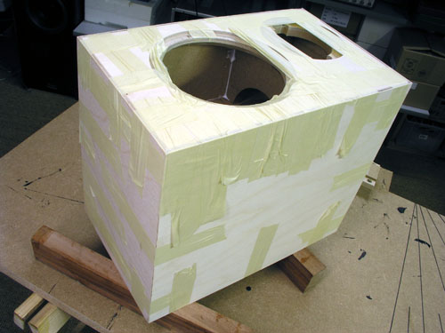
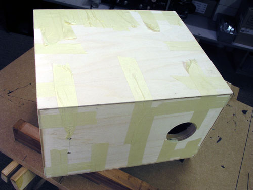
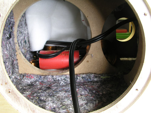
Cabinet construction images


I think this is the first time I used tape only for assembly. Works well if everything is cut to exact measures.

Cabinet damping
back to top

Add 10-13 mm felt to sides, top and bottom. Fold 170 x 200 mm 30 mm acoustilux and place behing bass driver in rear compartment. 
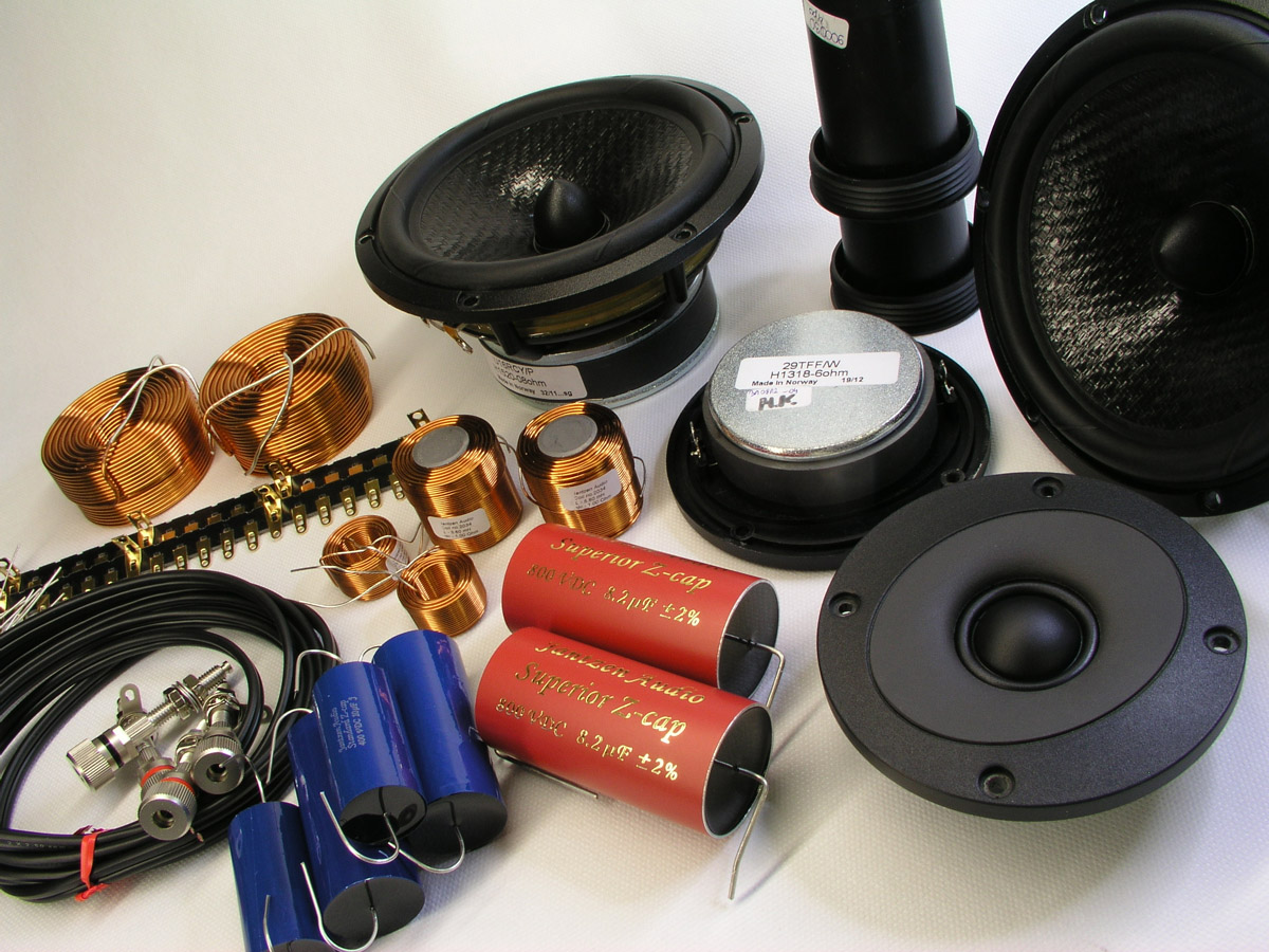

Complete Speaker Kit incl. drivers
back to top


Click images to view large. Damping material not shown.

For full quotation incl. shipping, please contact Jantzen Audio at contact@jantzen-audio.com
Remember to state where you live to calculate shipping cost.

All kit and component prices may be subject to change and are always to be confirmed by Jantzen Audio Denmark.

Download kit sales presentations:


All technical question at: troels.gravesen@hotmail.com


Measurements
back to top


Left: Intrinsic response of drivers on baffle. Pay notice to the smooth roll-off of midbass driver. This drivers just dies out towards higher frequences, most likely due to not having a dust cap. Dust caps add to the radiating area, but much too often also creates spurious peaks in the high-frequency domain.
Right: Response of drives driven from v2 crossover. The tweeter produces an almost text-book LR2 roll-off towards lower frequences.


Left: Again, the response from v1 and v2 displaying the impact of the notch-filter. 
Right: Point of crossover is 2.2 kHz as can be seen by reversing tweeter polarity, blue graph.

Left: Speaker response with R1011 = 4R7.
3R3, 3R9 and 4R7 delivered with the kit. System sensitivity is ~85 dB/2.8V/1 meter, midband range.
Right: Final system impedance. Green = electrical phase.


Click right image to view large.


Click images to view large.

Crossover Layout
back to top


Crossover board made as compact as possible to be inserted through bass driver hole.
Place vertical in lower compartment to allow access to terminals.
If all STANDARD Z-caps are used, the board can be made even smaller.


Crossover wiring
back to top

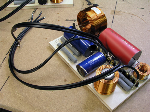
Getting the crossover in place proved more difficult than first anticipated. Take these steps:
1. Assemble the crossover before gluing the cabinet.
2. Assemble the cabinet with tape and try placing the crossover through the hole in the bracing.
3. Round corners of crossover board as seen here.
4. Mount the crossover before the terminals and damping material.
This way you should be safe.


Click images to view large.