|
Left: The
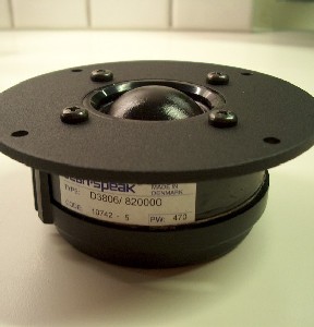
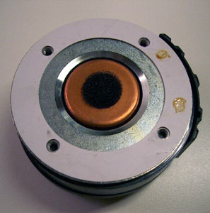
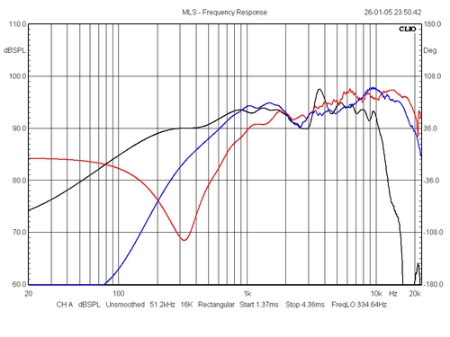
frequency response of the D3806 driver (blue) is not that
flat, but it is easily equalised to gain a flat response
up to 15 kHz. This driver can almost be used as a
stand-alone tweeter. I guess some damping material on the
pole piece might do well.
Right: D3806/8200 impedance profile (green). The copper
plating of the pole piece appears to do its job producing
an almost flat impedance response from 1500 Hz to 22 kHz.
The impedance peak around 900 Hz may be taken care of. So
much for the driver.
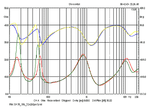 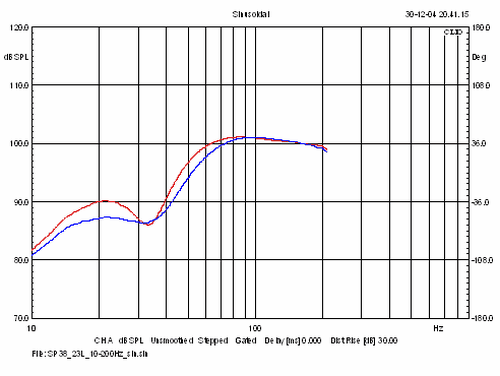
Left; Green = 33 litre volume, vent = 72 x
200 mm. Red = 23 litre volume, vent 46 x 200 mm.
The vent tuning of the 23 litre cab didn't exactly hit
the 33 Hz target, more like 35 Hz but let it be. As can
be seen the damping of the 8531 driver is increased from
going to 23 litre volume, i.e. smaller peaks (vent too
small?) and a better phase profile = easier load on the
amplifier.
Sinusoidal measurements (right image above) suggest we
have more bass from a 33 litre cabinet - and this is also
how it appears when listening to music, but it's very
hard to determine which is best. What strikes the most is
the difference in sound - there's an enormous difference
in sound from the two drivers. The bass from the 23 litre
cab may sound more dry and "fast", but I may
use the phrase "fast" because I know it's
supposed to be fast. The sound of a kick-drum from the 33
litre cab just sounds deeper.
The impact on midrange presentation is hard to ignore.
Going from 33 litres to 23 litres has an immediate
presence effect on the midrange and I'm not sure which
one I like the most. From the 33 litre cab the midrange
may sound a little dark and retracted where the 23 litres
gives a very forward sound pulling vocals right up to the
front of the speaker with subjectively reduced depth.
Hmm.... This is tough! Actually I think I would prefer
something in-between. Say 28 litre and same vent
tuning.....
More on sound
Making A-B tests from a variety of music
on the 23 litre and 33 litre cabinets didn't give any
conclusive results, but I'm in favour of the sound coming
from the 33 litre cab being more round and deep. The
upper bass and lower midrange appear to have more weight
and remember, we're still dealing with a relatively small
speaker here.150 square centimetres membrane area is the
determining factor for the scale of sound we can expect
from a basically two-way floorstander.
The general sound is just what it appears to be from the
SPL-graph shown above. It's direct and there's a lot of
detail - and three-dimensionality is indeed very good. As
is often the case from speakers with very flat response
profiles this is likely to produce excessive sibilance
from certain recordings. Sibilance mostly is related to
level, not quality, so in most cases this can be taken
care of by proper attenuation. There are so many things
the shown crossover does right, so I've been reluctant to
make major changes to this basic set-up - and I won't
even try making a series crossover for comparison. But
read on... Plus/minus 1-2 dB in the 2-8 kHz range can
make a world of difference to how we perceive the overall
sound from a loudspeaker. In the good old days - which
were not always as good as we may think - loudspeakers
often had two L-pads for adjusting the midrange and
tweeter level. L-pads were banished in any
"true" hifi connection claimed of deteriorating
the sound and maybe they did, I don't know. But depending
on the electronics in front of the speakers and not to
forget the room acoustics, most speakers often need minor
adjustment of overall tonal balance to suit the actual
set-up. But it has to be said that these L-pads were
mostly used to produce a loudness effect, i.e. turning
down the midrange - because the midrange is always the
most troublesome area - and turning up the tweeter to
give some highs. "Tizz-and-boom" - and without
the help of the speaker constructor. But we're not going
to use L-pads - definitely not.
Raising the 3806 series resistor from 1R0 to 2R2 removes
some of the forwardness sometimes coming from this driver
from less than supreme recordings. And the super-tweeter
needs further attenuation for matching the upper treble
level and 6R8 is replaced by 10R. So, now the overall
balance is more in line with the BBC-dip philosophy.
However, this may suit my ears and it's easy and no-cost
to make your own preferred voicing from making these two
changes. Valves - being more tolerable - may prefer the
1R5 or 1R8 to the 3806. Changing the 13-20 kHz region
doesn't chance the sound noticeably, but for the sake of
order....
I liked the sound from this set-up very much and was
planning to make all the measurements needed for
publication. I never was quite satisfied from the
phase-tracking between the 18W/8531 and the D3806/8200.
The SPL response was nice but inverting the polarity
didn’t produce the desired dip around the point of
crossover. So, time to analyse the whole thing a little
more closely and doing so by the LspCAD, http://www.ijdata.com/, revealed that a
4th order crossover topology might be better
suited to meet the target phase tracking.
The "problem" with the LspCAD is that you in a
short time can produce dozens of crossovers that has to
be tested sonically. The good thing is that when your
basic measurements of the individual drivers are done
right, the software prediction is usually what you get.
For once calculations and the real world appear to join
hands.
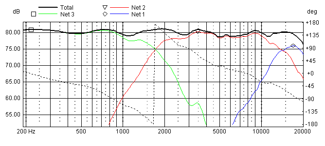
Predicted response from crossover.
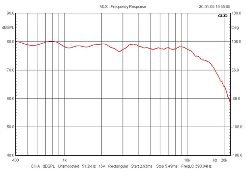
Actual response from crossover, 8513 not included.
The final cab
drawings
BACK TO
TOP
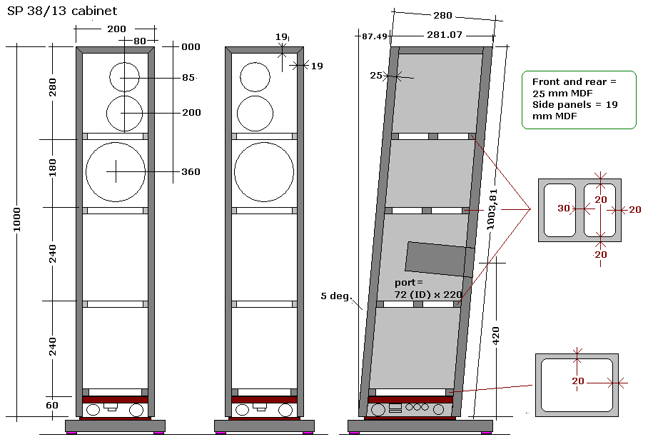
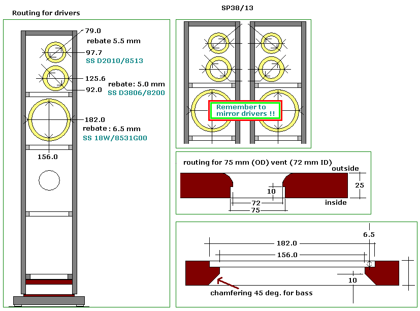
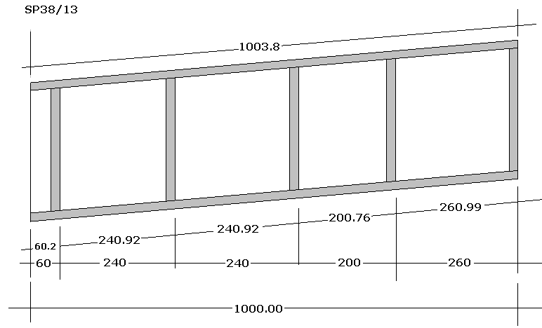
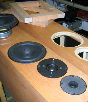
After having decided on cabinet
construction the following drawings were made and the
tests cabs were modified to off-set the 3806 and 8513
tweeters as depicted above. Quite some task to modify the
test cabs but worthwhile before handing over the drawings
to the cabinetmaker. This time I won’t make the
final cabinets myself.
Cabinet damping:
Please read here general advise
on damping of a 24-32 litre floorstander:
http://www.troelsgravesen.dk/cabinet-damping.htm
CROSSOVER
BACK TO
TOP

SP38/13 crossover schematics.
SPEAKER KIT
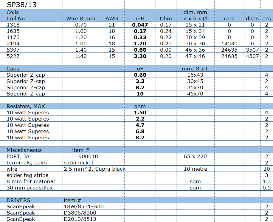
You can buy the kit with or without the
drivers - or some of the drivers if you already have some.
Please ask
Jantzen Audio for
options.
All kit and component prices may be subject to
change and are always to be confirmed by Jantzen Audio Denmark.
Download Complete Kit
Sale Presentations:
 Discontinued
All technical questions to
troels.gravesen@hotmail.com
All questions regarding purchase of
kits, please mail Jantzen Audio at
contact@jantzen-audio.com
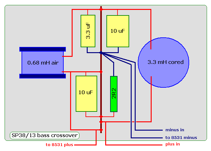
Bass section layout.
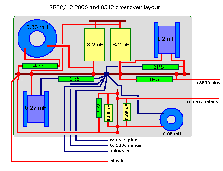
Mid-tweeter section layout
Measurements
BACK TO
TOP
Measurements
are not normalised for 2.8V/1 meter, thus do not reflect
system sensitivity.
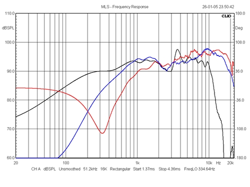 
Left: SPL from individual drivers again.
Black = 8531. This is a damar coated 8531 showing a dip
at 3 kHz and a peak at 3.7 kHz and the lesson to be
learned from this is to be prepared to all sorts of
surprises when you apply coatings. No problem in this
construction due to low point of crossover between 8531
and 3806, but this wouldn't work in a 2-way system with
higher point of crossover. Blue = 3806 and red = 8513.
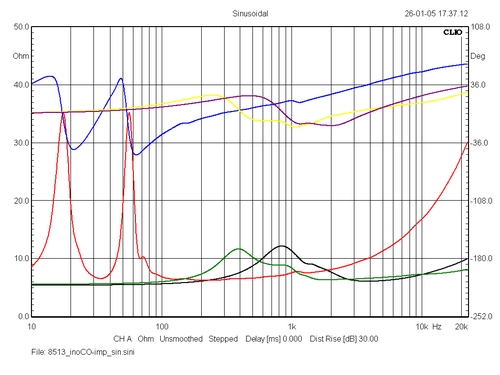
Right: Impedance of drivers, already
commented above.
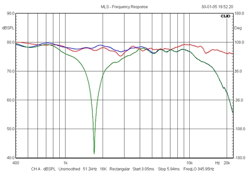
Left: Red = overall system response. Blue
= same without supertweeter. Green = inverted 3806
polarity. Right: Wavelengths at 13 kHz are short, very
short and moving the microphone just a little up and down
easily creates dips at point of crossover between 3806
and 8513. Fortunately this is very hard to hear.
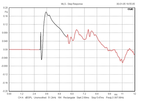 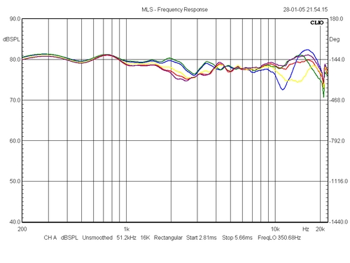
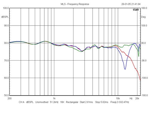
Left: Step response. Right: Vertical dispersion at +/- 5,
10 and 15 deg.
Comments to measurements:
As discussed before, don’t pay too much attention to
what is going on above 10 kHz. The wavelengths are so
short here that moving the microphone only one centimetre
up and down will make a completely new picture.
I was pleased to see that the middle treble response was
smoothed by off-setting the tweeters, so apparently there
was something to the suspicion on wavelength and cabinet
width interfering here. The overall impedance profile
looks good. Minimum impedance is about 6 ohms and the
phase angles are not severe. A fairly easy load I should
say.
Sound:
As always, the most difficult part. This is a very
neutral sounding speaker. Due to the very flat response
profile a good tonal balance is heard from instruments
and vocals. This is not always the case. Only a minor
“BBC-dip” here. The bass is deep and articulate
– exceeding the 2.5 clone. It’s also a quite
revealing speaker and it will tell you right away the
quality of your source material.
Getting the 8531 down to about 70 cm above floor level
helped in giving the acoustic scenario a more realistic
position in my listening room. I always felt a bit uneasy
from having the ever so important midrange either too
high or too low relative to my listening position.
This speaker has a great level of transparency and throws
a wide soundstage and is going to be my reference for my
two-way designs – because this is basically a
two-way design with added supertweeter.
SP38/13
construction pictures
BACK TO
TOP
Here are a number of pictures taking
during mounting the vent, adding damping material and
mounting drivers and crossovers. A vent tuning discussion
will appear at: http://www.troelsgravesen.dk/vent_tuning.htm, as I here have
tried various flanged and flared vents to measure the
impact on performance.
>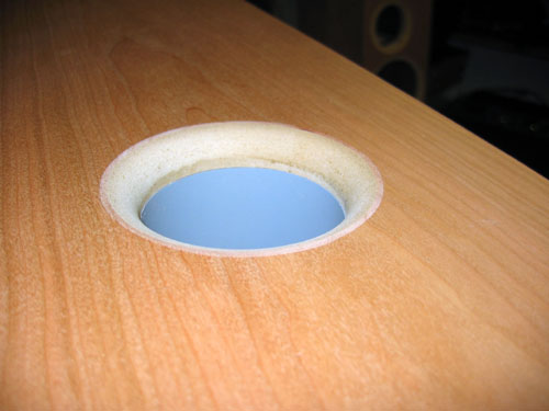 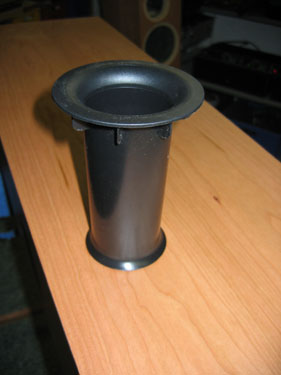
Left: Flaring of vent opening. Right: Alternative vent.
Vent tube = 180 mm x 72 mm (ID), Fb = 36 Hz.
Right: Monacor BR-60TR vent: ID = 54 mm at inlet, 60 mm
at outlet. Length = 140 mm. This actually works fine and
produces a Fb of 34 Hz.
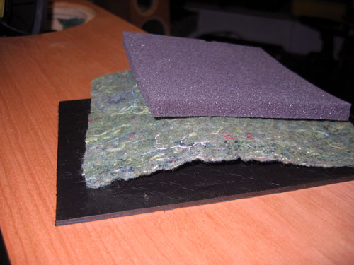 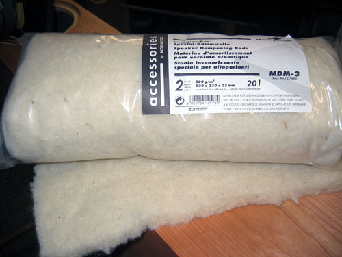
Damping material used. 4 mm self-adhesive bitumen pads
added to all internal panels. This adds considerably to
the weight of the enclosure. Above approx. 12 mm felt
material. This is probably a mixture of cotton and
polyester material made into felt sheets. This is what
I'll be using for the SP38/13. Alternatively I use 10 mm
heavy polyester foam also added to all internal panels.
Last but not least I use this great material - MDM-3
– a mixture of sheep's wool and polyester, also from
Monacor. Used for additional damping at top and bottom of
cabinet - and right behind the 8531 driver.
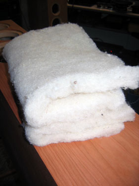 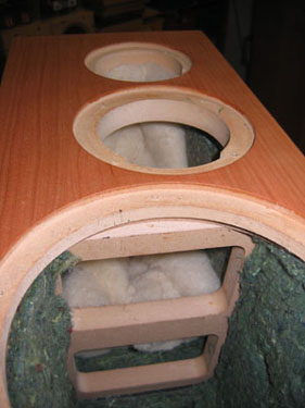 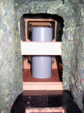
Left: One sheet of damping material cut into two, folded
and placed behind 8531 driver. This may change during
final voicing of the construction.
Middle: ½ roll MDM3 placed at top of cabinet.
Right: A look into the cabinet from bottom. No crossover
applied yet. Vent is glued in place
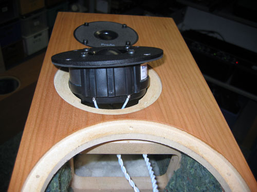 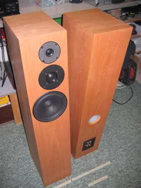
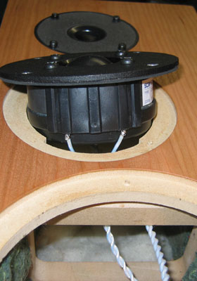
Left: 3806 dome and supertweeter getting in place. Right:
ll drivers, vents and terminals in place.
 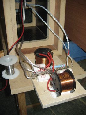
Left: Crossover for bass shaping up. Right: Attaching
wires for bass.
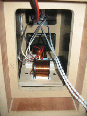 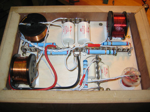
Left: Bass crossover in place inside cabinet. Right: 3806
and 8513 crossover at bottom of cabinet.
SP38/13 Superior Z-caps
July
2008
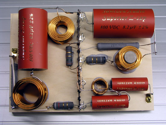 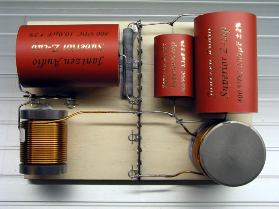
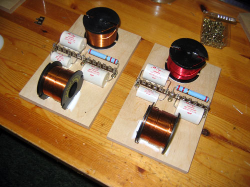
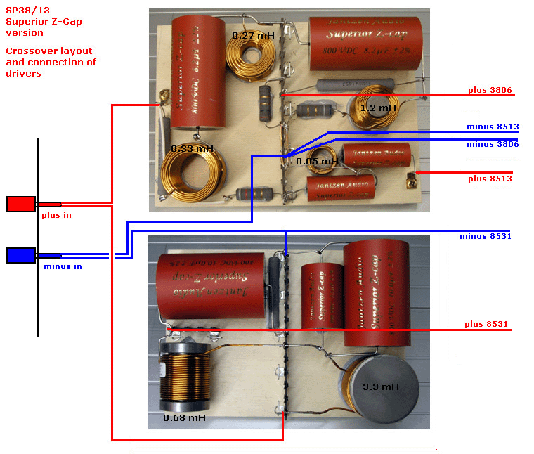
| Left:
Tweeter crossover section realised with Superior
Z-Caps. Right: Bass crossover section realised
with Superior Z-Caps. Having a
complete set of drivers for the SP38/13, I made
these crossover for a Norwegian guy buying the
drivers and finished crossovers.
This is what it should have looked like, had I
had the Sup. Z-Caps back then.
Crossover
layout is different from what seen above due to
the size of the capacitors. Both boards are 125 x
180 mm, 12 mm Baltic birch.
|
BACK TO
TOP
|
