ScanSpeak 3WC-C Vifa
PL11 edition
Copyright 2016 © Troels Gravesen
Go to on this page:
DRIVERS
CROSSOVER
CABINET
MEASUREMENTS
Discontinued from Jantzen Audio.
Kit instruction with schematics and parts list can be bought
from me at 75 EUR.
Payment by PayPal to my account:
troels.gravesen@hotmail.com
This speaker is very similar to the
ScanSpeak 3WC-C (13M) version released recently.
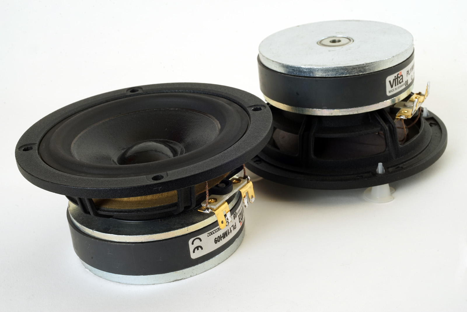
Only difference is the middriver being the Vifa PL11MH09-08, one of most
smooth sounding drivers we can find. Actually the small magnet version,
PL11WG, was so smooth it could be run without a low-pass filter at all.
The large magnet MH version display a smooth roll-off at both ends and
makes a perfect midrange driver for this 3-way system.
Driven within its operating range, this is a speaker you can listen to
for hours and hours without fatique.
Basics:
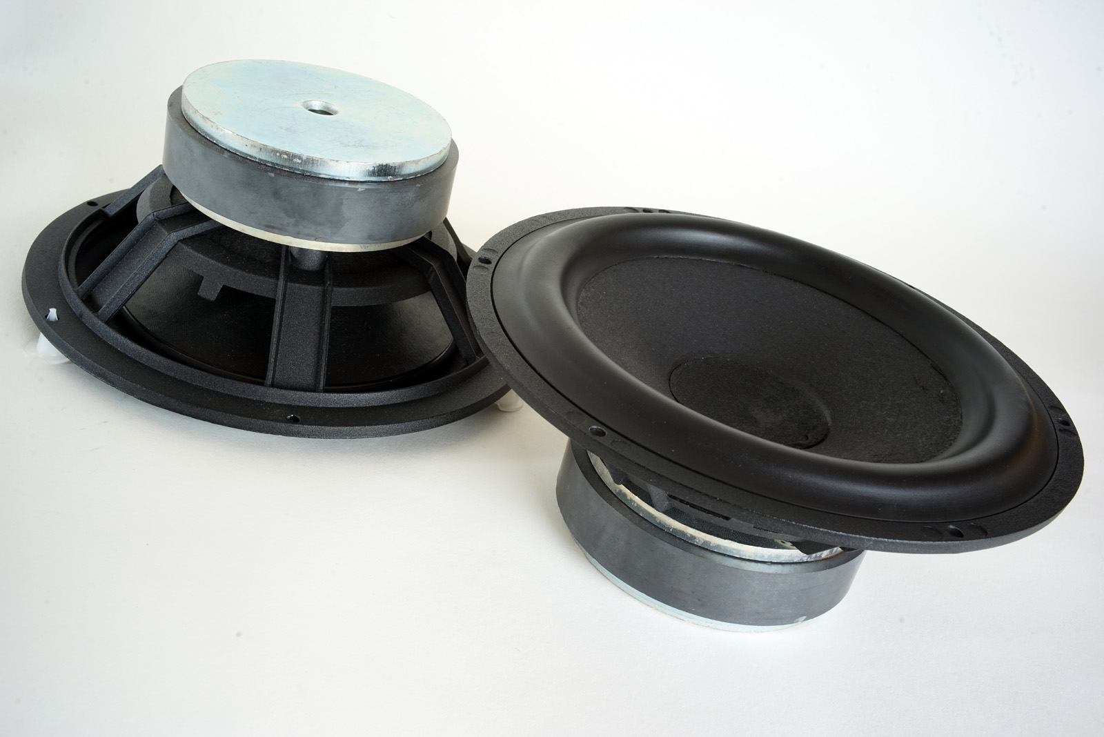
3-way vented system from 1", 4" and 8" drivers.
Cabinet dimensions: 30 cm (W) x 38 cm (D) x 60 cm (H)
Points of crossover: 650 Hz and 2300 Hz, low-order LR2 filter topology.
System sensitivity: ~86 dB.
Impedance: 8 Ohms.
Power requirement: 50 wpc minimum, but depends on required playback
level, room size and amplifier power supply.
Power handling: 160 watts, please also read this:
http://www.troelsgravesen.dk/power-handling.htm.
Any burned driver is a misused driver!
Please note: Any change to front panel design and drivers' placement and you're on your own and need a new crossover - and I can't help. Please read here.
The Kit
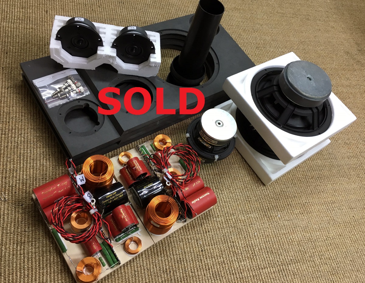

Click images to view large
Download specs here:
21W/8555-00 Vifa PL11MH09-08
R2604/833000
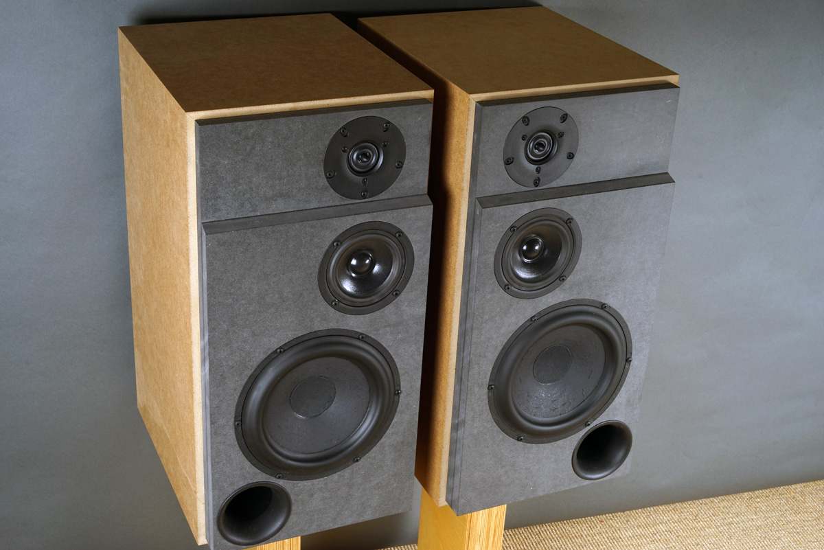
Here the final speakers in raw MDF.
Crossover components' values comes with purchase of the kit.
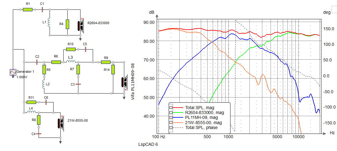
The basis topology is 2nd order LR2 for all sections and make perfect summation when tweeter is some 20 mm behind midrange driver.
The crossover topology is the same as for the 13M version, but values for the midrange coils and resistors are different.
Complete crossover schematics can be bought from me for 75 EUR (PayPal), should you have the drivers at hand.
Write troels.gravesen@hotmail.com
The Kit Instruction will be sent by email.

Click image to view large
Simulation
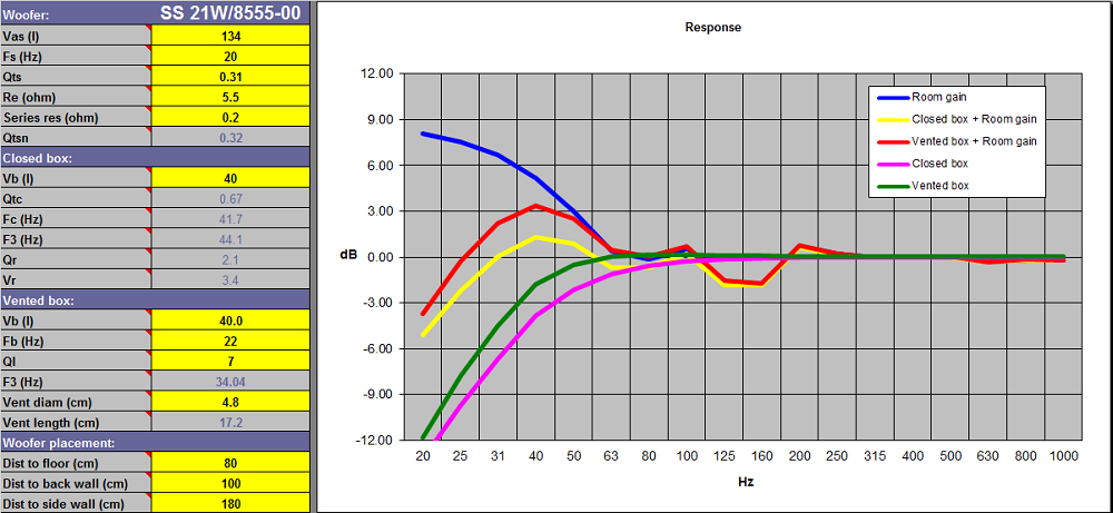
Bass cabinet simulation
From the workshop
Now, I won't repeat all the images of five former 3-way classic. Please visit frontpage and find construction images, e.g. SBA-3WC, very similar to this one: http://www.troelsgravesen.dk/SBAcoustics-3WC.htm#CABINET. This goes for damping as well.
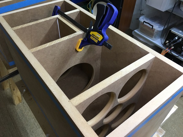
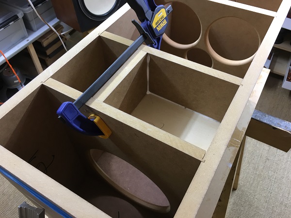
Cabinet was constructed from 19 mm standard MDF and braces and mid-cab from 16 mm MDF. Glue the mid cab before anything else. This helps a lot in keeping everything else in place when doing the final gluing. I fact, I only use tape to assemble these cabs.
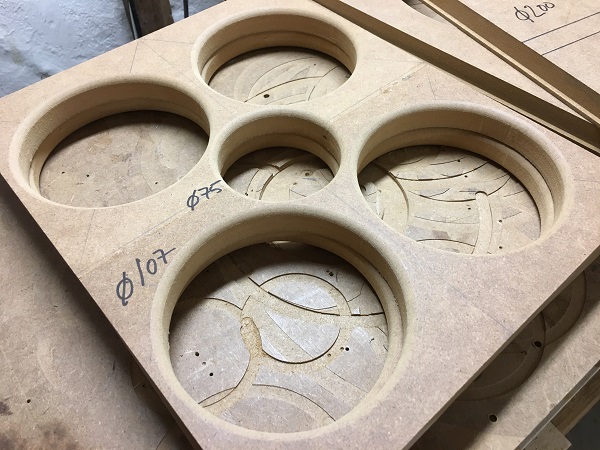
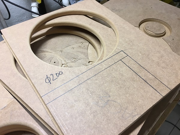
Please find hole dimensions for the braces above. To the left the bottom
brace, to the right the two braces supporting the midrange cabinet.
Everything that
can be counted does not necessarily count; everything that counts cannot
necessarily be counted". Albert
Einstein.
A few comments on MEASUREMENTS before
you start interpreting all the readings below.
First of all, if we think measurements will tell us how a speaker
sounds, we're wrong. The perception of sound is way too subjective to be
reflected in any measurements we can perform. A loudspeaker system is
meant to give us a satisfying idea of an acoustic event and for some
people a pair of 5 USD ear-plugs are enough, others spend 200 kUSD on a
truly full-range pair of speakers - and the latter may not be happier
than the former.
Measurements may give us an idea of tonal balance of a system, i.e. too
much or too little energy in certain areas. Measurements may tell us
about bass extension if far-field measurements are merged with
near-field measurements. In addition to this, ports may contribute to
bass extension. Most of us diy'ers do not have access to an anechoic
room for full-range measurements from 20-20000 Hz.
What cannot be seen is what kind of bass performance we get in a given
room. Bass performance is highly dependent on in-room placement of your
speaker and the same speaker can be boomy in one place and lean in
another. Actual SPL level at 1 meter distance and 2.8V input is useful
for en estimate of system sensitivity and combined with the impedance
profile may give an idea of how powerful an amplifier is needed to drive
the speaker to adequate levels.
What measurements do not tell is the very sound of the speaker unless
displaying serious linear distortion. The level of transparency, the
ability to resolve micro-details, the "speed" of the bass, etc., cannot
be derived from these data. Distortion measurements rarely tell much
unless seriously bad, and most modern drivers display low distortion
within their specified operating range.
Many people put way too much into these graphs and my comments here are
only meant as warning against over-interpretation. There are more to
good sound than what can be extracted from a few graphs. Every graph
needs interpretation in terms of what it means sonically and how it
impacts our choice of mating drivers, cabinet and crossover design.
What measurements certainly do not tell is the sonic signature of the
speaker, because speaker cones made from polypropylene, aluminum,
Kevlar, paper, glass fiber, carbon fiber, magnesium, ceramics or even
diamonds all have their way of adding spices to the stew. Nor do
measurements tell what impact the quality of the crossover components
add to the sound, from state of the art components to the cheapest of
coils and caps, they all measure the same if values are correct.
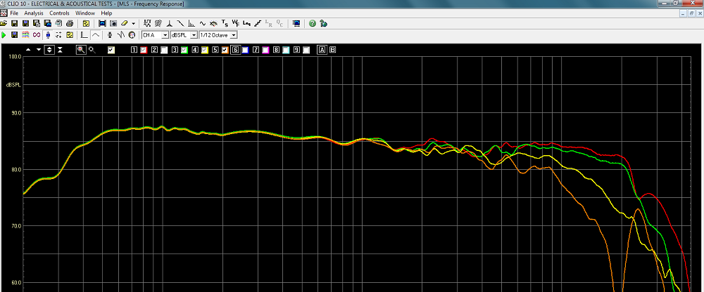
Above the response from 0, 10, 20 and 30 deg. off-axis.
Readings merged with near-field response of bass driver @ 200 Hz.