TQWT/DTQWT-10/DTQWT-12 mkII
T35 option
Copyright 2013 © Troels Gravesen
GO TO: CROSSOVER CROSSOVER LAYOUT MEASUREMENTS SPEAKER KIT

Click images to view large.
Download driver data files: SEAS T35C002
When the SEAS T35C002 dome was released in Europe I ordered a
pair to see if they would fit the TW034 waveguide because due to the
rear chamber it might do the same thing as the modified Audax TW034 dome can
do: Go lower and allowing the point of crossover between 8008 and dome
tweeter to be taken down to around 2 kHz providing a bit more presence and
better dispersion in upper mid and lower treble.
The T35 does not
sound anything different from the TW034 dome; in that respect they're too alike.
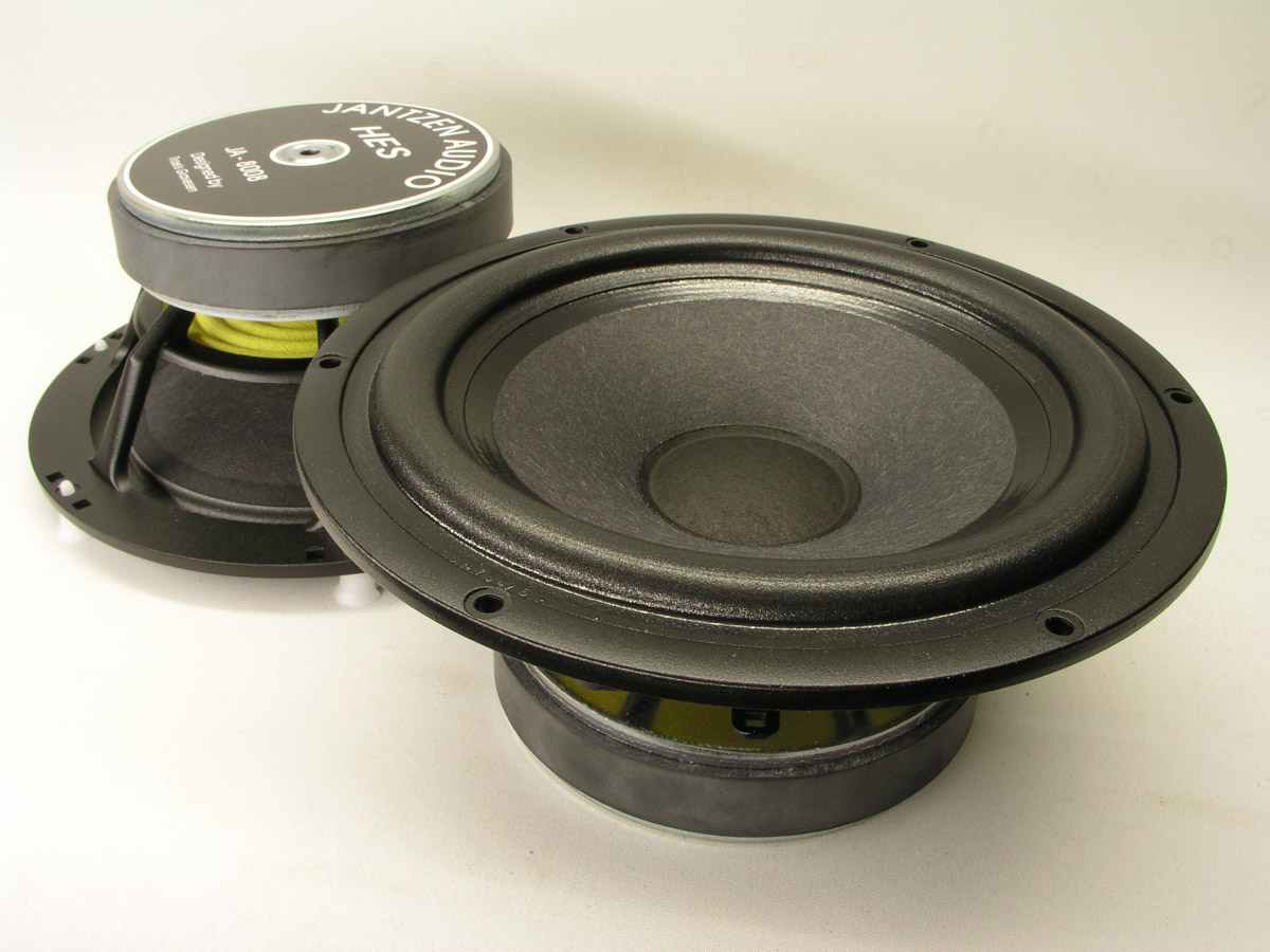
The SEAS has a voice coil diameter of 35 mm, the Audax 34 mm, fabric weave
slightly different, coatings very much alike, dome shape very much the
same, etc. Only major difference to the standard TW034 is the rear
chamber.
Any difference in sound is based on minor differences in
frequency response and this can be corrected in the crossover. I've used
my modded TW034 the same way as I now use the T35 but never released an
alternative version of TQWT and DTQWT as very few people have the
tools to do the TW034 modifications. No point in making a speaker only a
very few people can copy. It has to be said the TW034 can be used
un-modified with the same T35 crossover with a minor dip around 2 kHz
but it's no big deal - if audible at all.
I suggest taking a look at performance of
the T35C002 and modified TW034
here. Study
the waterfall plots and you'll find very little difference.
Click image to view large
Making a seamless integration of an 8" driver
and a dome tweeter is the trick, regardless of being a 1" or 1½". The
T35 - as is - can easily handle the treble range down to even 1.5 kHz
from a LR2 filter - and it was tried and it didn't sound right. No
matter what, the treble stood out and the T35 just kept calling: Here I
am! And it wasn't due to point of crossover, slopes or levels, but due
to the transition in dispersion from a large 8" driver to a small dome. It
didn't produce the coherent sound of the TQWT and DTQWT speakers fitted
with the TW034/waveguide.
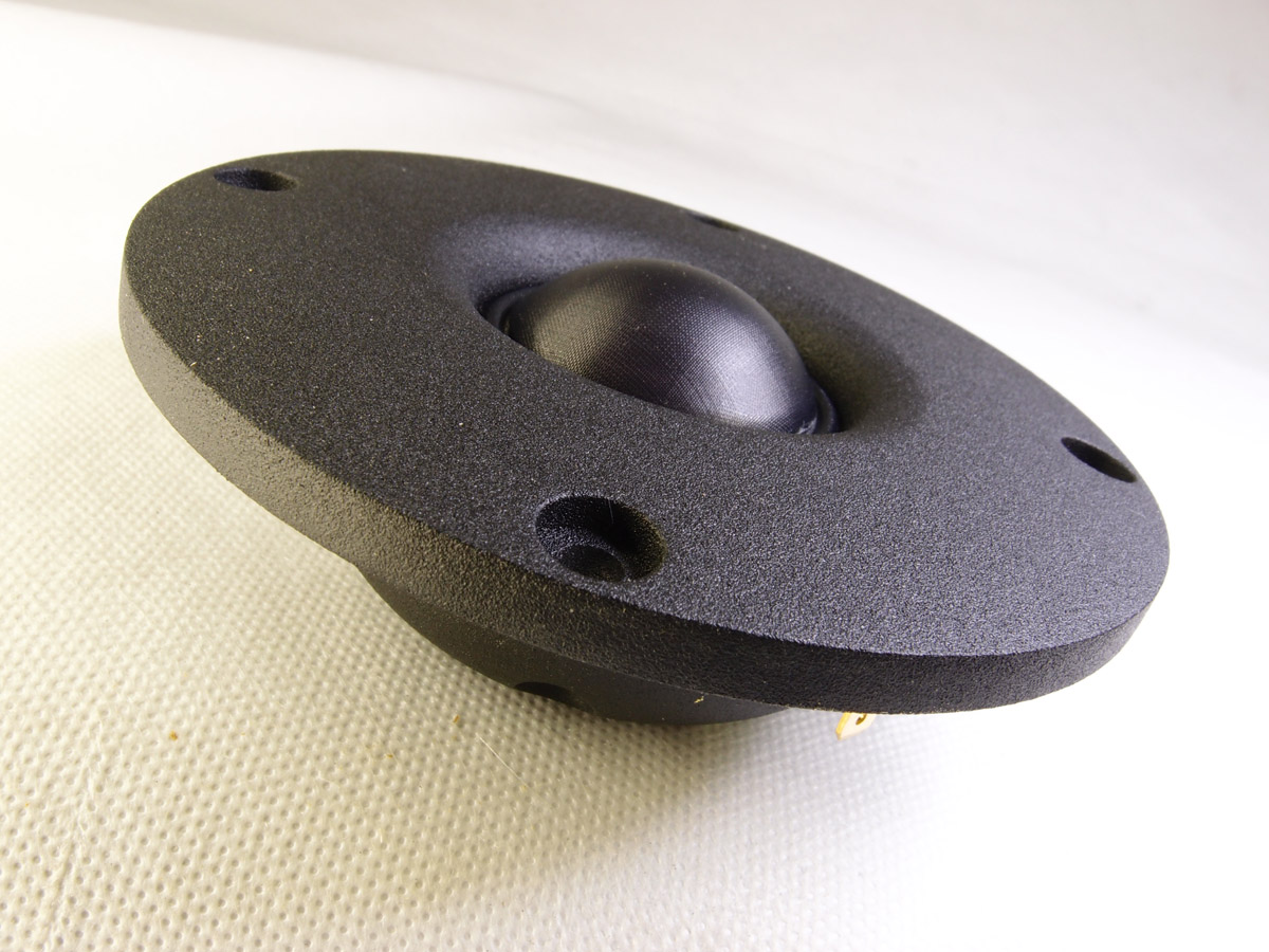
So, a pair of waveguides were brought in and threads were made to allow
mounting of the T35 by the four screws holding the face plate. Here we
remove the T35 face plate and mount the tweeter directly to the
waveguide.
Back to measurements, simulation and crossover fine-tuning.
With a point of crossover at 2.1 kHz an even simpler crossover could be
achieved compared to the standard DTQWT crossover and now it started
sounding right.
Finding the right tweeter attenuation is important and in fact takes
quite some time as we are easily seduced by detail from an over-emphasised
treble level. I ended up with 1011 = 2.2 ohms.
Should you want to change your current TW034 for the T35 you can also
fasten the T35 dome by making a flange like I did for the ScanSpeak 7100
tweeter. Click
here
to see how. I used the flange for my initial testing. But you then have
to be able to make threads for the screws and need a 4 mm thread forming
tap, hand taps.
What the new crossover does is two things: More
presence in upper mid/lower treble due to better dispersion of sound,
hence more detail. It kind of brings the music a little better into the
room, where the mkII more provides a window to the music to somewhat
exaggerate the difference. I have chosen not to call this a DTQWT mkIII
as the basic crossover topology is the same, only the point of crossover
has been lowered to 2.1 kHz.
Now, should you rush to change your DTQWT mkII crossover and buy the T35
tweeter also? Maybe, maybe not. The change is sound is significant, but
only your ears can tell which one you like the best.
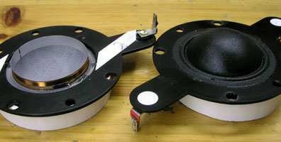
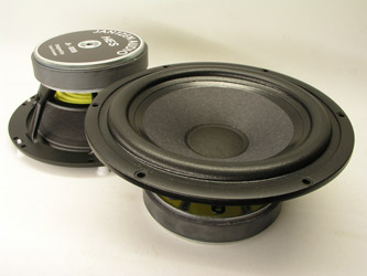
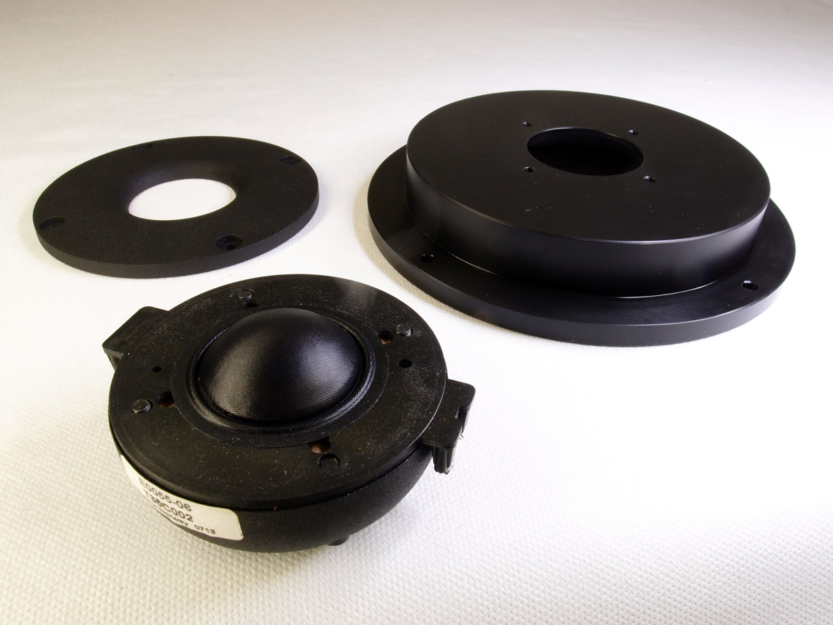
From left: T35 rear/T35 front/TW034-rear-front
The T35 dome including surround
is actually slightly smaller than the TW034 dome, probably about 0.8 mm
difference in diameter despite having a 1 mm larger voice coil, but
nevertheless fits perfectly into the TW034 waveguide. Only problem is
making four threads that will take the four screws holding the standard
T35 front plate. I never succeeded doing this properly by hand and
eventually mounted the T35 dome with a flange, the same used for the ScanSpeak 7100 dome.
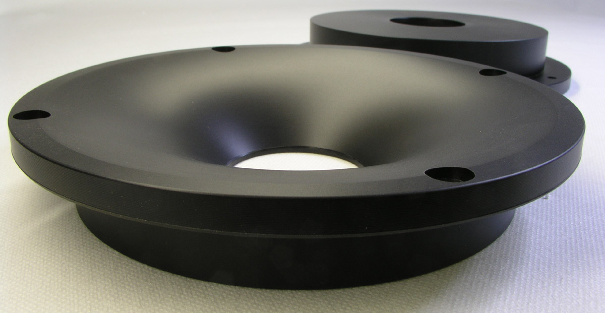
When the next batch of waveguides were ordered I went to the factory
and had them make a batch of waveguides suitable for the T35 dome.
Thus, only thing to do is loosen the four screws, remove the face plate
and fasten the T35 to the waveguide. Tighten the screws with caution!
Firm - but no more. If you have a box of 4 mm thread taps, the diameter is 60.4 mm and the threads need
to be effective down to 4 mm. Drill to 5 mm depth and you won't
penetrate the waveguide.
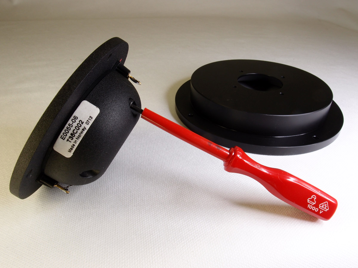
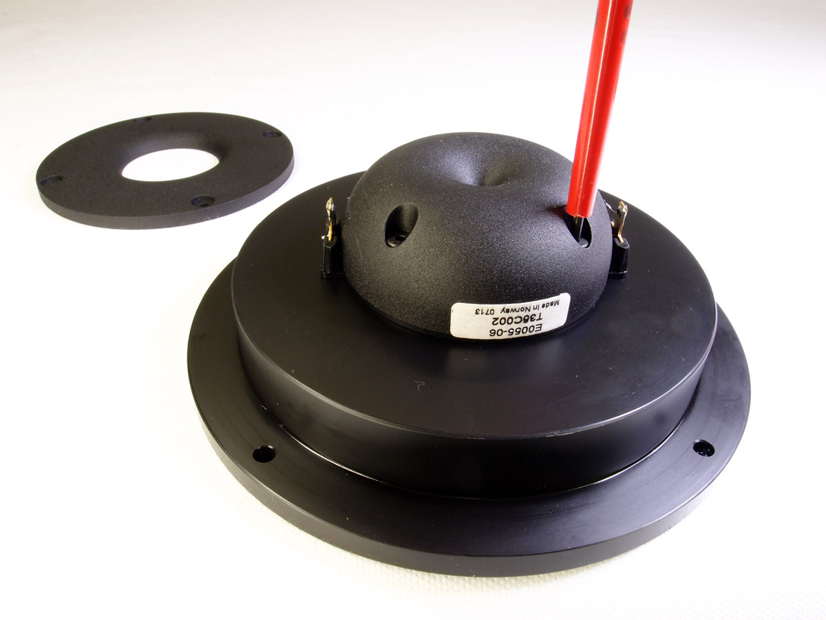

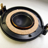
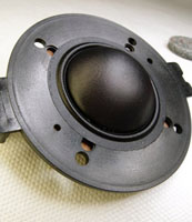
From left to right the procedure in removing
SEAS front plate and attach dome to Jantzen Audio waveguide. Click images to view large.
The Crossover
back to index
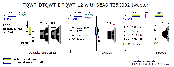
Simulation is one thing, practical experience
quite another. This turned out even more simple than I had hoped for.
2nd order on the electrical side and a perfect LR4 topology on the
acoustical side with positive polarity on all drivers. Point of
crossover is 2.1 kHz.
An LCR filter on tweeter impedance peak turned out
unnecessary. If you're wearing belt and suspenders use (4R7 + 68 uF +
1.0 mH) in parallel to the tweeter (before R1041).
The bass driver crossover is really 1st order but residual midrange
response is filtered acoustically by adding felt discs in front of
drivers like the DTQWT-mkII.
For the TQWT you leave out the bass section.
If you want to try out the crossover topology before investing in T35 -
or stay with the TW034, you can add 5.6 uF in parallel to the 6.8 uF
capacitor in the 8008 section. This makes 12.4 uF and is fully
acceptable. Obviously you need new coils for L2011 and L1031 and 6 pcs
1.0 ohm, 2 pcs 1.5 ohm and 2 pcs 2.2 ohm resistors.
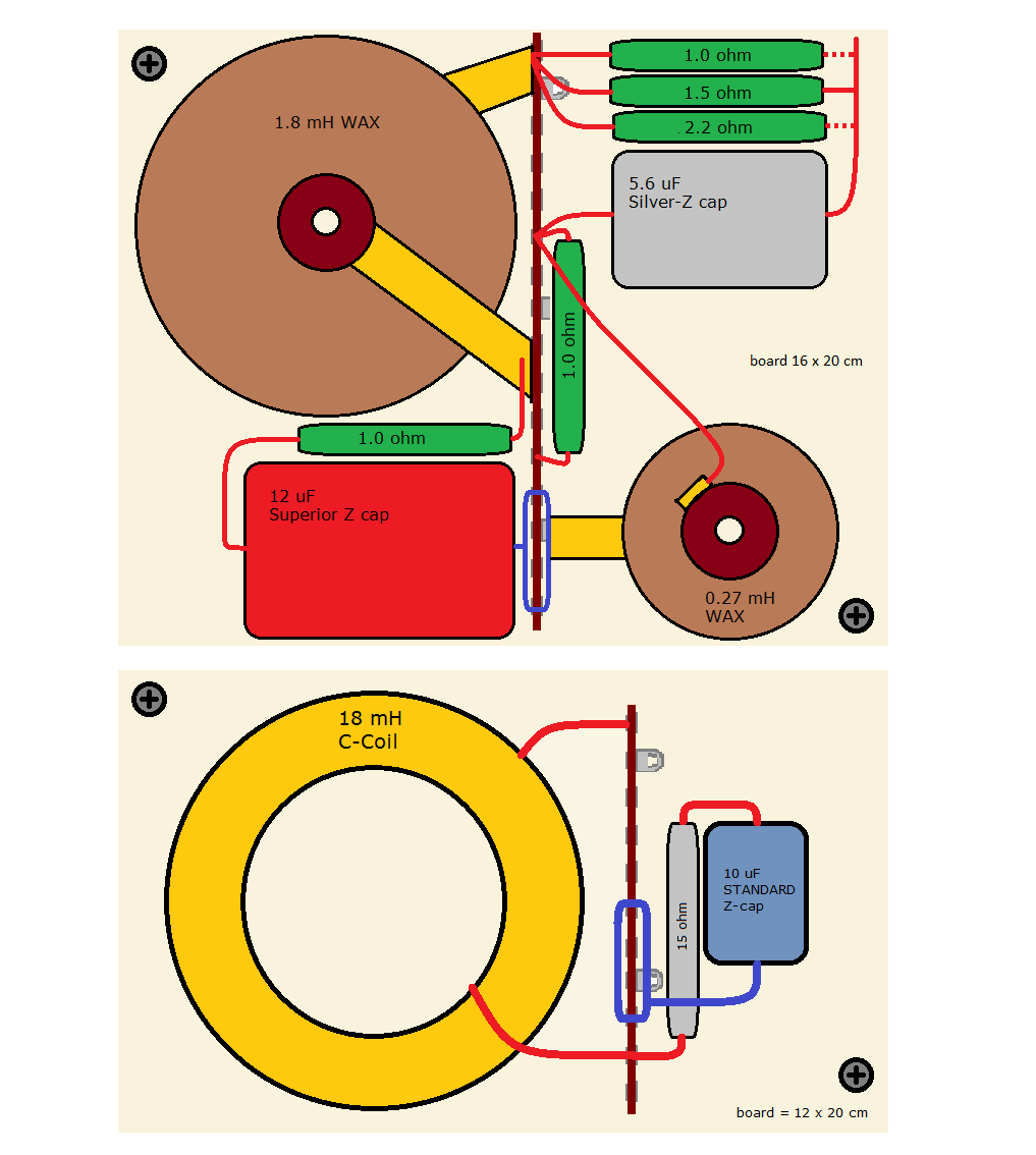
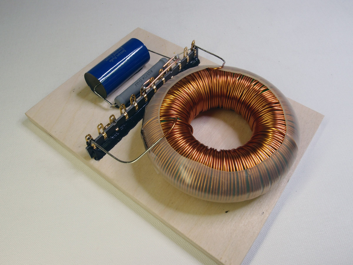
Crossover layout
back to index
Click image to view large.
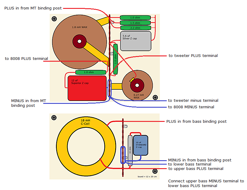
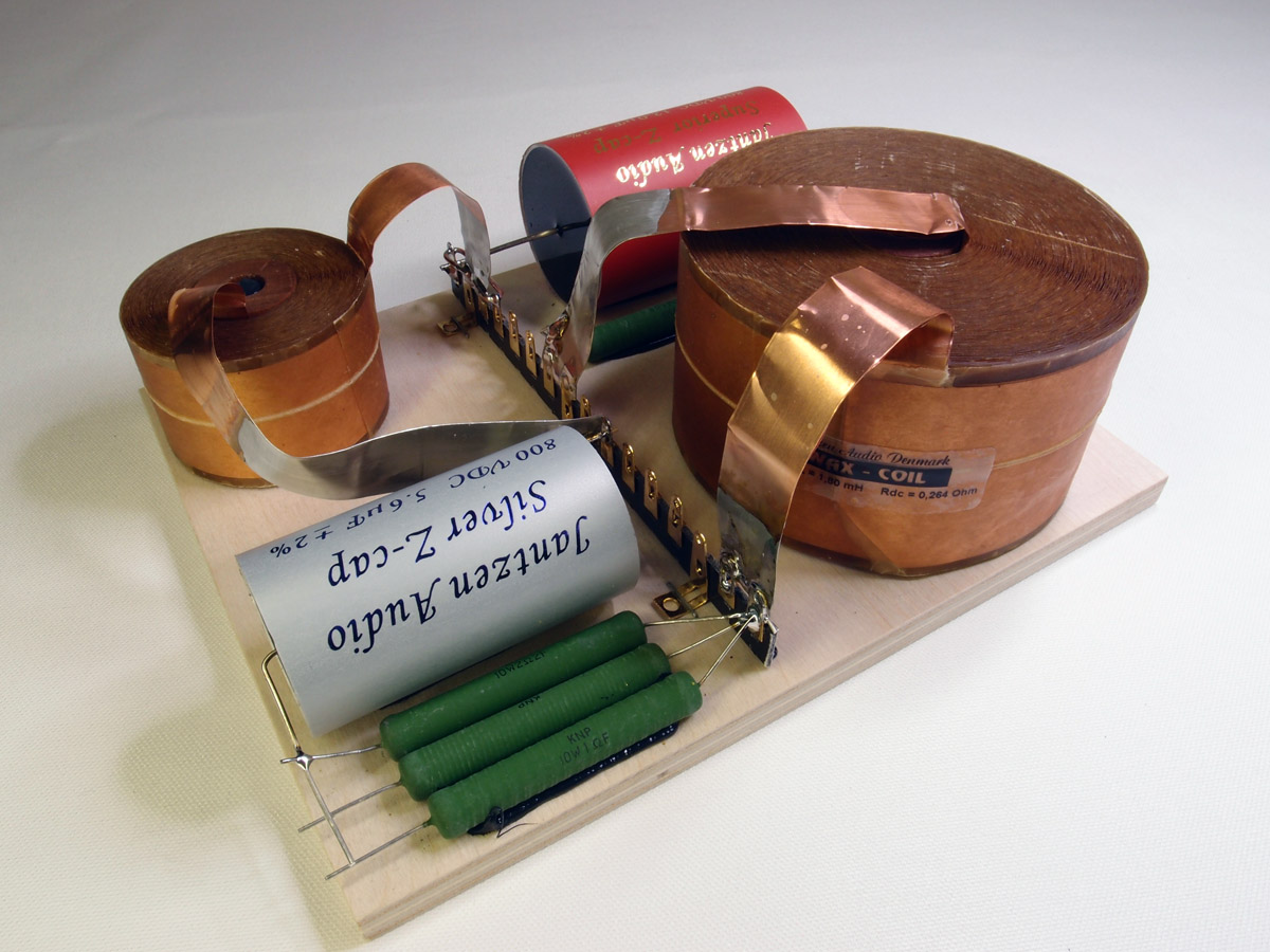
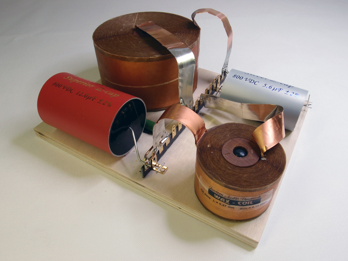
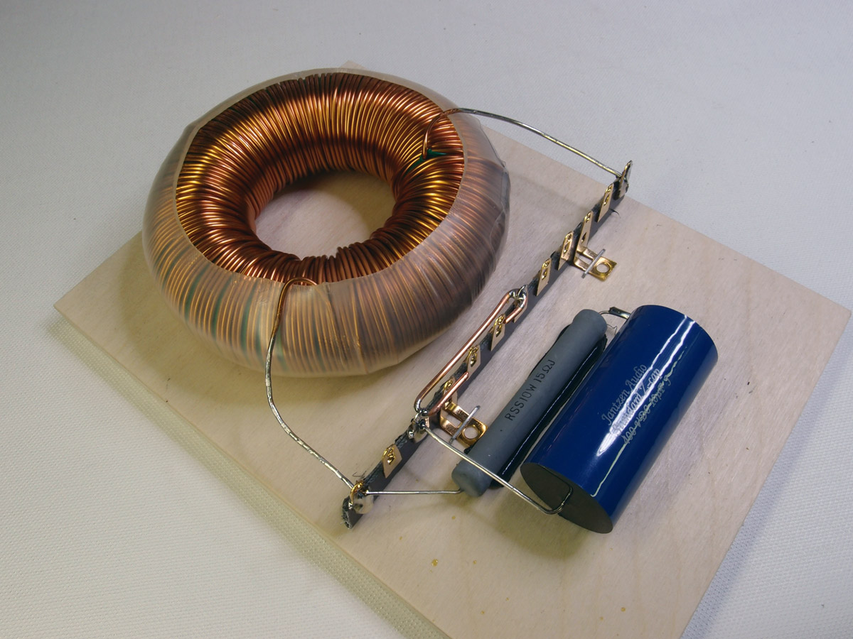
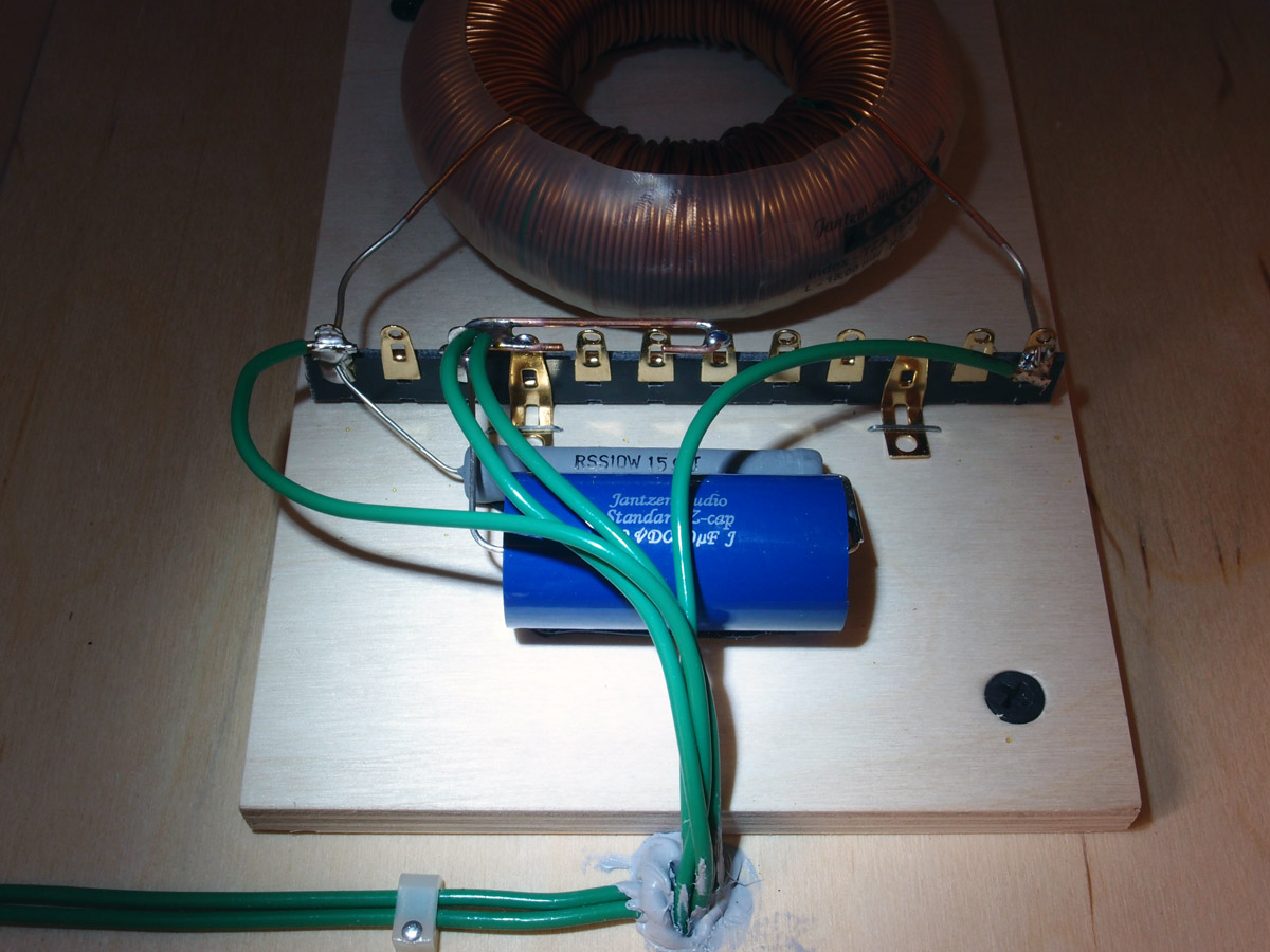
The finished crossovers. Above for the mid-tweeter, below for the bass
drivers. Click images to view large.
Please note R1041 is missing on the board here (tweeter series resistor,
was added later)
The 8008 series WAX coil is quite a chunky beast with its 1.8 mH
inductance.
A smaller (500 watt) C-coil has been chosen for the bass drivers as
previous C-coil was wildly oversized due to availability of suitable
cores.
With 95 dB sensitivity the current C-coil is still overkill with a 500
watts capacity.
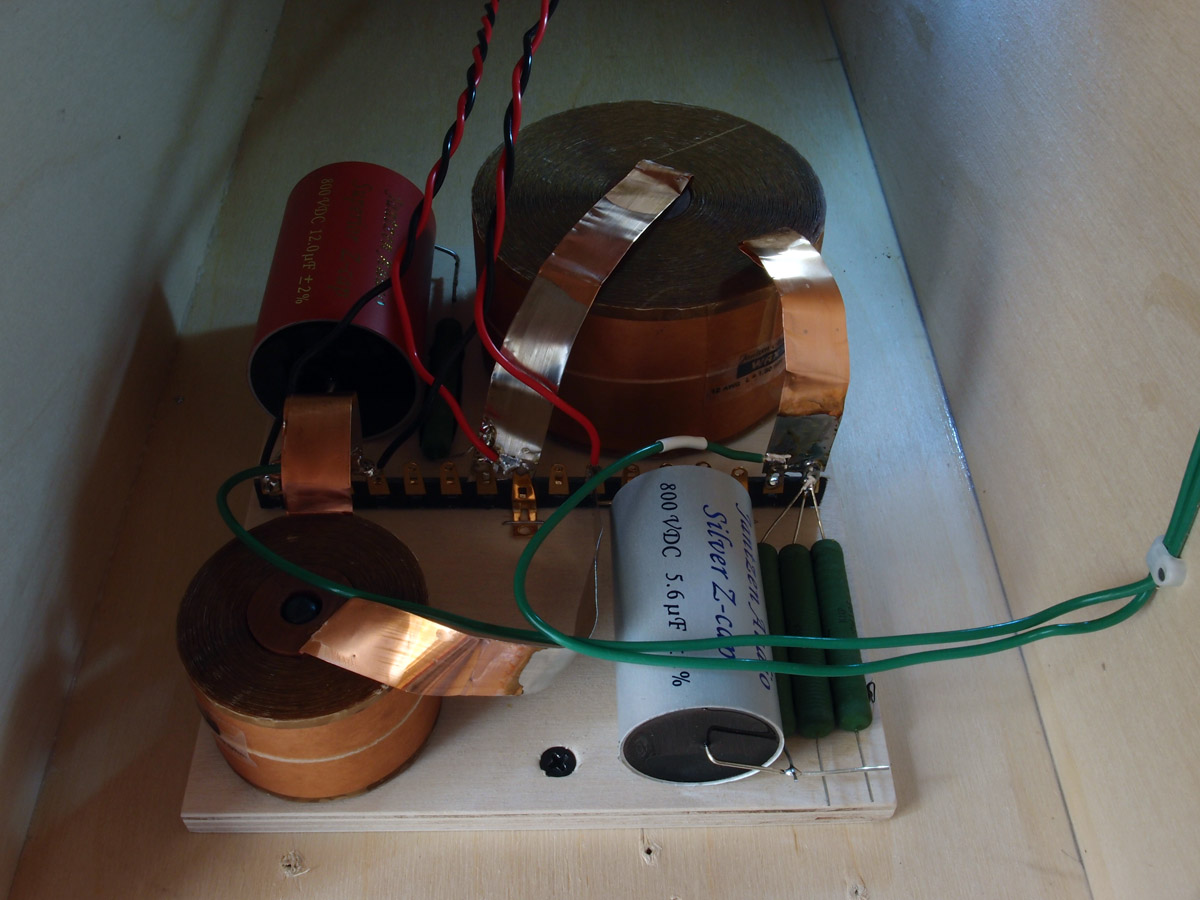
Crossovers mounted in cabinet. Bass crossover on rear inner panel and
mid-tweeter crossover on front inner panel.
Click images to view large.
Measurements
back to index
Measurements may give
us an idea of tonal balance of a system, i.e. too much or too little
energy in certain areas. Measurements may tell us about bass extension
if far-field measurements are merged with near-field measurements. In
addition to this ports may contribute to bass extension. Most of us
diy'ers do not have access to an anechoic room for full-range
measurements from 20-20000 Hz.
What cannot be seen is what kind of bass performance we get in a given
room. Bass performance is highly dependent on in-room placement of your
speaker and the same speaker can be boomy in one place and lean in
another.
Actual SPL level at 1 meter distance and 2.8V input is useful for en
estimate of system sensitivity and combined with the impedance profile
may give an idea of how powerful an amplifier is needed to drive the
speaker to adequate levels.
What measurements do not tell is the very sound of the speaker unless
displaying serious linear distortion. The level of transparency, the
ability to resolve micro-details, the "speed" of the bass, etc., cannot
be derived from these data. Distortion measurements rarely tell anything
unless seriously bad and most modern drivers display low distortion
within their specified operating range.
Many people put way too much into these graphs and my comments here are
only meant as warning against over-interpretation. There are way more to
good sound than what can be extracted from a few graphs. Every graph
needs interpretation in terms of what it means sonically and how it
impacts our choice of mating drivers, cabinet and crossover design.
Left: The two T35 domes mounted on waveguides. Rigth: Individual and
summed response from drivers driven from crossover.
Point of crossover = 2100 Hz.
Left: Tweeter response from R1011 = 0.47, 1.0 and 1.5 respectively, I
use 2R2.
Right: Response from inverting tweeter polarity.
Left: Horizontal dispersion at 0, 10, 20, 30 and 40 deg. Right: CSD at
25 dB scaling.
Speaker Kit
back to index
For full quotation
incl. shipping, please contact Jantzen Audio at
contact@jantzen-audio.com
Remember to state where you live to calculate shipping.
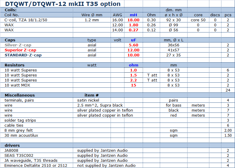
Download kit sales
presentation for DTQWT
mkII (10" & 12") T35 option:

All kit and component prices may be subject to change and are always to be confirmed by Jantzen Audio Denmark
All technical question at: troels.gravesen@hotmail.com
TQWT mkII T35 version
For full quotation
incl. shipping, please contact Jantzen Audio at
contact@jantzen-audio.com
Remember to state where you live to calculate shipping.
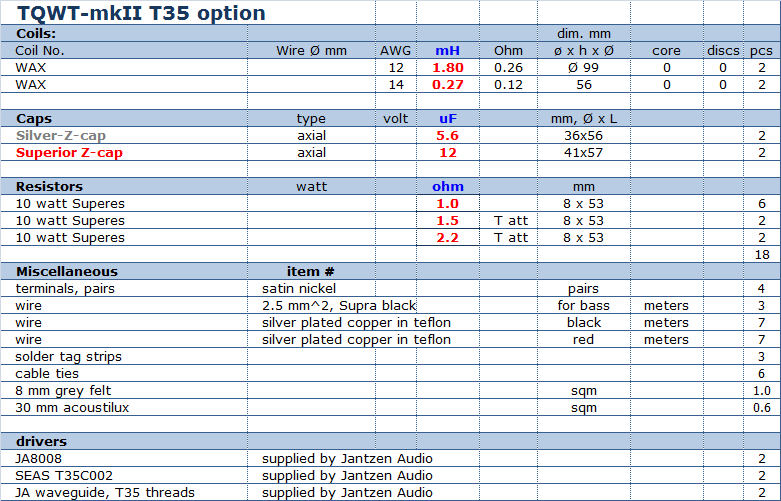
Download kit sales
presentation for TQWT-mkII T35 option:
All kit and component
prices may be subject to change and are always to be confirmed by
Jantzen Audio Denmark
All technical question at: troels.gravesen@hotmail.com
