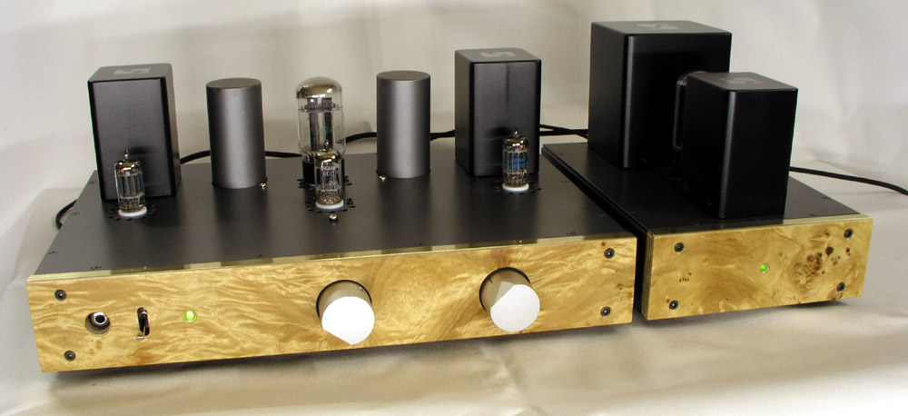
A very long
journey into making a line stage amplifier |
Next to my
vdh Colibri cartridge and vdh phono
stage, this 6N6P w.o.t.
line stage is the best thing that has entered my
hifi system ever. Trying out the TRAM with my
Audio Mirror monoblocks and later GlowMaster KT88 amplifiers has been a true
revelation. I'm afraid to say it even beats my
300B integrated by a small margin in overall
dynamics and an almost palpable midrange that
reaches out into my listening room.
I had no idea what I was
in for when I borrowed the TRAM, but
after a few minutes of listening, there was no
doubt in my mind that I had to build a similar
line stage. Cloning the TRAM isn't particularly
difficult having the amp and assembly instruction
at hand. The TRAM, as-is, has serious hum
problems and I was sure I could handle this by a
better layout and a DC filament supply for the
5687 tubes, but things turned out to be not that
simple. Read on.
All transformers from SAC
Thailand: http://www.sacthailand.com/
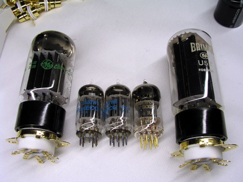
5687 tubes
Initially I bought JAN Philips 5687 tubes
for my line stage. Michael/DK gave me a pair of National
5687 and
thanks to John/Utah/US, I now have a wide selection of
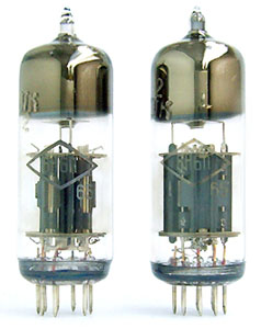
5687 tubes including a 5687 substitute, the Dutch Amperex
7119.
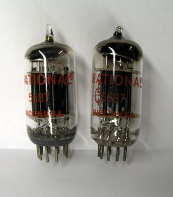 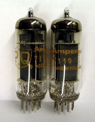 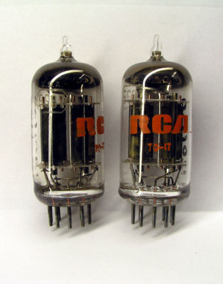
Left: National 5687. Middle: Amperex 7119
(Herleen, Holland Amperex "PQ"). Right: RCA
5687
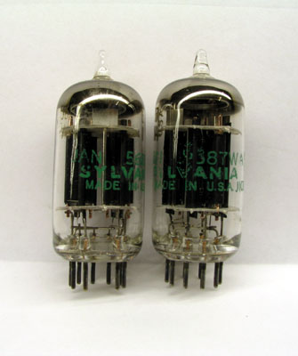 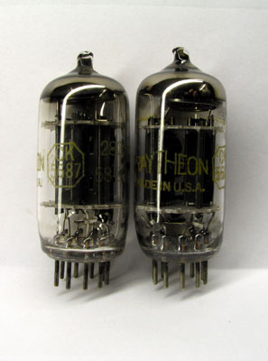 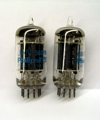
Left: Sylvania 5687. Middle: Rytheon 5687.
Right: JAN Philips 5687
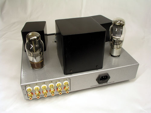
How it all started
- the TRAM line stage from DIY-HiFiSupply, Hong Kong
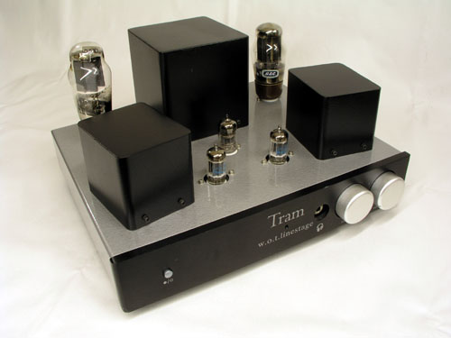 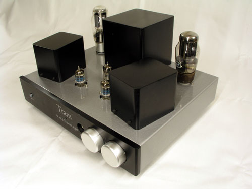
Tubes: PSU: 5Z3, 6AS7, ECC83. Amplifying
stage: 2 x 5687 JAN Philips.
Interstage trafos: Origin not known. 10k
primary, 0-300-600 ohms secondary. Phones from 300 ohms
tap.
The TRAM has some lay-out drawbacks. One is the ECC83
placed far away from the 6AS7 tube, though closely
interlinked.
Next all tubes are heated by AC and I think this is one
reason for serious hum problems. The use of un-shielded
signal
cables may pose another problem and based on the
experience presented here, I would re-build the entire
TRAM. As-is it
simply can't be used with 95 dB speaker systems. 90 dB
and a dead-quiet power amp may go, but that's about it.
(Changing filament supply to DC helped
somewhat, but the main problem is likely to be the mains
transformer being too close to everything).
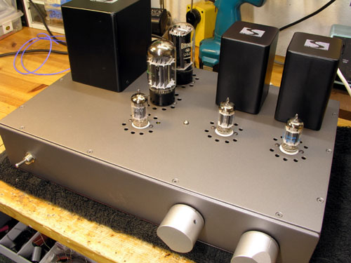
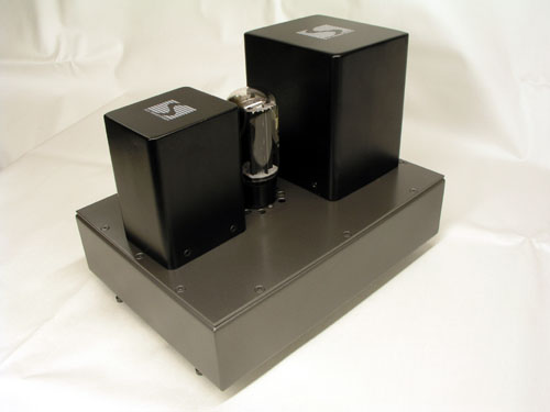
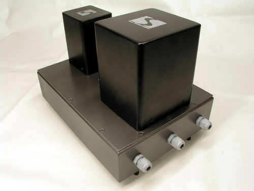
My 5687 W.O.T. line stage project:
New layout for wot line stage.
Cabinet dimensions will be 250 (D) x 400 (W) x 75 (H) mm.
Schematics
Complete schematics. Kiwame resistors and Obbligato film
caps used in most places.
In the final edition, the filament supply for the 5687
tubes will be changed to a regulated 12.6 V supply
with the two 5687 filaments in series.
For low efficiency speakers the above may work, but not
for 95+ dB speakers. Still some residual hum.
Please note: The red 100 ohms resistor was
not present in the TRAM circuit.
According to Peter Pan - a well know valve guru - this
resistor MUST be there to make the 3.3 uF Obbligato work
properly.
Valve pin configuration.
Components
.jpg)
.jpg)
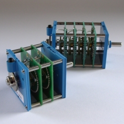
Left: Components piling up.
Right: Interstage trafo, 5k prim./0-300-600 ohms sec.
Supermalloy core.
.jpg)
.jpg)
Left: Interstage trafo. Right: Mains trafo.
 .jpg)
Left: 6AS7 GEC, JAN Philips 5687, ECC83
Electro Harmonix, BRIMAR U52.
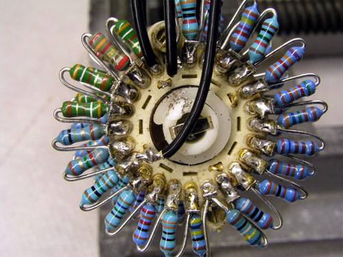
Right: 100k, 23 step latter type attenuator volume
control, Dale resistors (50 US $).
Out of three attenuators bought from Hong
Kong, three has been faulty. The nice looking one above
too.
Now, a rotary switch used for an attenuator has to be
shorting and turning this one up for the first time
made the poor test drivers' cone pop out of the magnet
gap and the voice coil stayed on the pole-piece...
Hmm....
Sorry Hong Kong dealers selling cheap China stuff, I've
had it. This was the last time.
I'll be trying a 41 step Acoustic
Dimension attenuator - and my never failing 100k
ALPS is doing the job until the AD arrives.
.jpg) .jpg)
Left: Obbligato 100 uF/400 V; this cap is BIG!
Right: Input selector 2 x 4
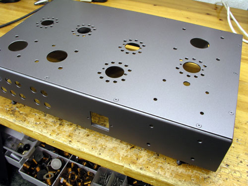
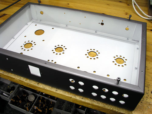
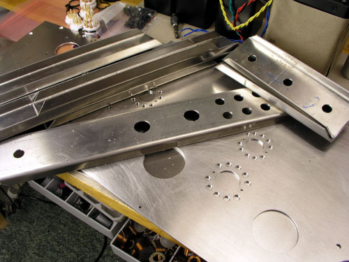
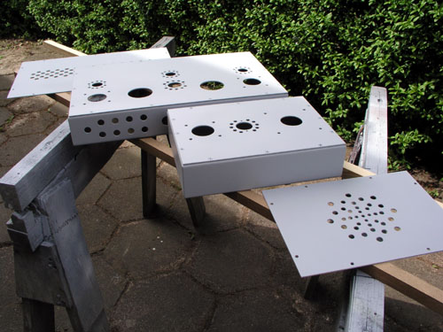
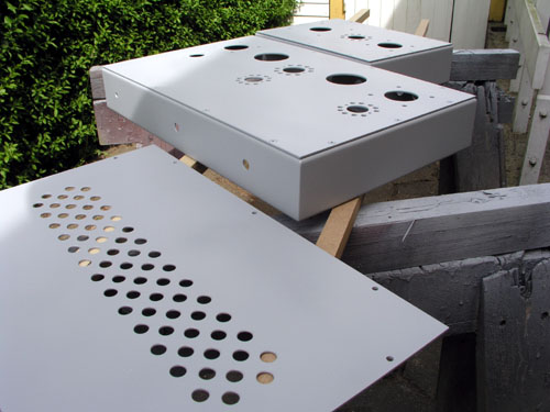
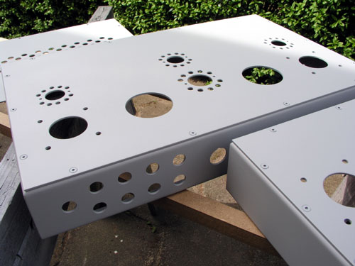
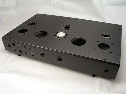
Cabinet construction
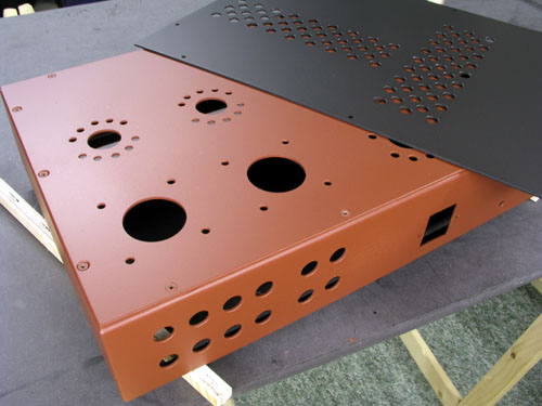
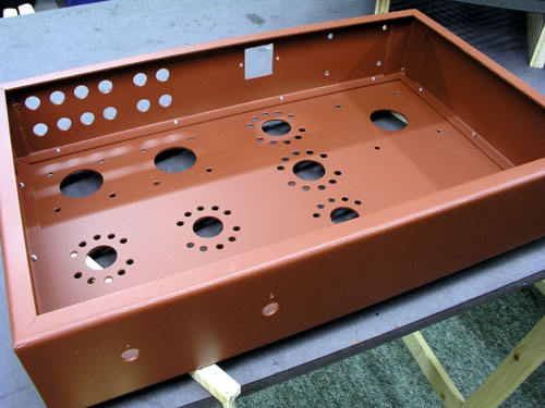
Cabinet made from 2 mm aluminium. Here
with red primer spray paint.
In the town where I live, Aarhus, we have a public
workshop, Huset (The House), with a metal
workshop, where I can bend the aluminium sheets.
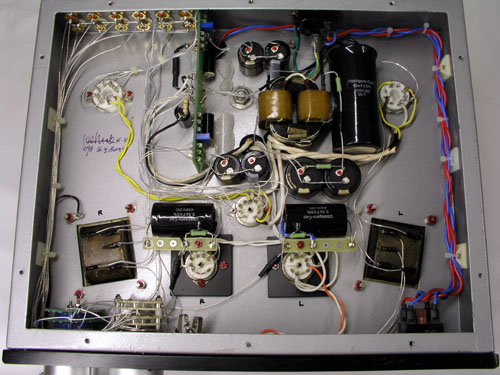
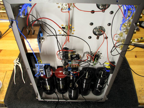
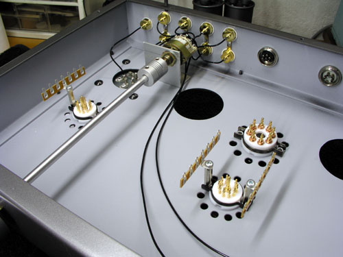
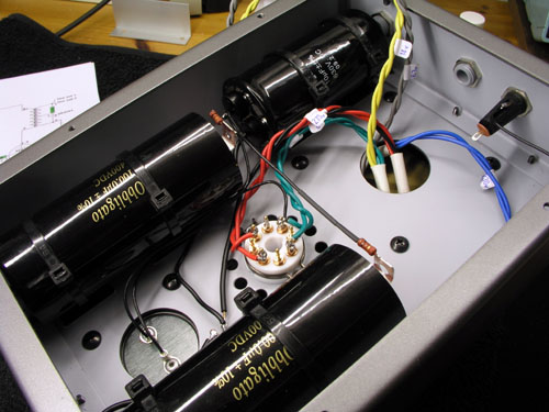
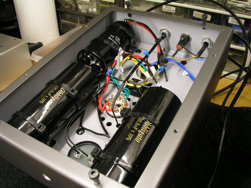
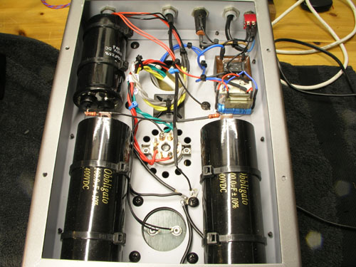
Assembly
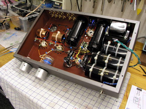 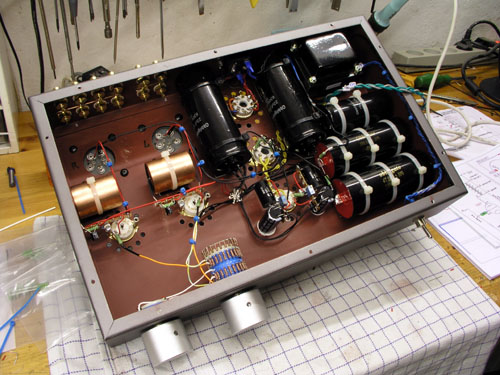
Power supply caps take a considerable
amount of space.
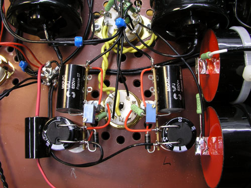 
Left: HT section, 6AS7 on top, ECC83 at
bottom.
Right: Amplifying stage, 5687 sockets and two 3.3 uF
Obbligato caps.
Only half 5687 is used (and heated) per channel.
Time to start thinking about front panel
design.
Hum has been a
serious problem with this line stage.
Having 95 dB speakers I need very low level noise
and the original TRAM was really noisy, something
that can be read on the web too if you google
"tram wot". AC is used for filament
supply in the original TRAM and from all similar
wot line stage constructions I have found on the
web, all have DC filament supply for the (5687)
tubes. Having ordered the mains trafo with 6.3
volt for this, I had to use a simple approach
rather than 7806/LM317 regulators, thus 2 x
10,000 uF caps as seen in the schematics. This
reduced hum considerably and one channel was
silent. The other channel still had unacceptable
hum levels (I use a 12" Altec 414C right in
my face on the workbench while working on the hum
problem). Moving wires around at any stage during
construction didn't make any reduction in hum at
all. Trying true start earthing of all ground
connections didn't help either. H(u)mm....
Some good advice on hum problems
can be found here at: http://www.vt52.com/diy/tips/tips_hum.htm
(my comments in red)
Causes
1a - the tube is pulling more current
than the cathode emission can handle.
Not the problem here. Have tried
increasing cathode resistor. No change in hum.
1b - the tube is resonating along
with one of the transformers by means of the
chassis or wiring.
Not the problem here.
1c - the ripple on the filament or
B+ power supply is too high.
Right channel is silent, so
filament supply and HT supply should be OK.
1d - the last capacitor in the
filament supply is too far away from the tube
itself.
Have tried adding caps right on
tube pins - didn't help.
Prevention
2a - use a separate transformer for the
filament supplies to prevent capacitive coupling
between windings.
Have tried external, heavily
regulated 6 V supply: No change in hum.
2b - make sure the power supply
for the filament has a ripple of no more than
5-10mV
- have to do something here. I
measure 55 mV. I'll try 12.6 volts, LM317T
regulation, and connect the 5687s in series.
2c - make sure the B+ supply does
not have a ripple greater than 20mV
- I measure less than 1 mV, can
this really be true?
2d - use star point grounding for
all components and inputs/outputs
Done. Still hum.
Damage
Control
3a - place a cathode bypass cap of about
1000uF...
Tried, doesn't help.
3b - use battery heating on the
filament...
Not tried.
3c - add more capacity to the B+
supply...
Tried. Doesn't help. (+150 uF
extra).
3d - remove the ground point from
earth/chassis and connect the two by means of a
100 ohm resistor...
Done. Doesn't help.
I
have built quite a range to tube line
stages and even RIAA amps in the past and I never
had serious hum problems - but..... I never had
the mains transformer on board, so to speak.
Adding a large sheet of aluminium between the
mains trafo and left channel output trafo reduce
hum, so maybe I made a bad cabinet layout after
all.
Removing
the mains transformer calls for some
serious redesign measures and 40 cm width may not
be enough for placing mains and output
transformers with enough distance. I could place
the output transformers sticking out on the left
side, but I don't want to make this line stage
look like a freak, so first of all I have to
remove mains transformer and connect via a 1
meter cable. Takes a lot of wires....
Removing
the mains transformer helped a lot and
it didn't need being meters away. Actually it
could stay on top of the chassis, but only turned
90 deg and close to the front. After this the
left channel had the same low hum level as the
right channel, but still a bit too much. Removing
the choke also from the inside to the top behind
the mains transformer helped somewhat further and
if I ran my Audio Mirror amps at 1 volt
sensitivity (currently at 500 mV), I'd probably
be where hum level is acceptable. That is, I'm
not sure the AM amps are really dead quiet - or
the RIAA for that matter. But, sitting 2-3 meters
away from the DTQWTs, I don't want to hear any
noise at all. Nothing.
So,
time to reconsider the whole project. Right
now my w.o.t. line stage looks like something out
of a junk yard, and while I'm recovering from the
many late night hours fighting the hum war - and
cleaning the workshop that looks like a
battlefield - I'm now at least enjoying
Anne-Sophie Mutter playing Bach - without hum in
the quiet passages.
|
2nd cabinet layout
Alu sheets have
been ordered for a new version with
separate power supply unit. I'm not a fan of
having the lower shelves filled with power
supplies, but the 5687 line stage is so good,
I'll tolerate almost anything.
Before the new cabinets
are finished, more experiments are being
performed. Looking through the wot line stage
constructions that can be found on the web, none
of these had the capacitor connecting B+ and
cathode resistor. I'm not sure about the
rationale behind this capacitor, but removing it
is an obvious option.
Before even doing so, I had some kind advice from
Peter/Acoustic
Dimension on this:
In my first preamplifier with the 5687 + OPT, I
also used a separate power supply. Still you have
to be also careful that the OPT’s don’t
pick-up anything from power transformers from
other equipment. There are 2 things I would
test to see if the sound can improve still
further. Remove the 3,3uf Obbligato across the
tube and OPT. Use a higher value resistor, for
example 1K2 or no resistor at all (but then you
have to test the frequency response and see if it
is still OK) I will look now and then to your
progress!
So, the 3.3 uF cap was removed and frequency
response was measured 1) with 3.3 uF in place, 2)
without 3.3 uF + 620R load and 3) without 3.3 uF
+ 1.1k load. Graphs seen below. With the 3.3 uF
cab in place we have a rather early roll-off
below 100 Hz, which didn't in any way render the
line stage low in bass response, but without the
cap it surely looks better; within 1 dB from 20
Hz to 20 kHz.
|
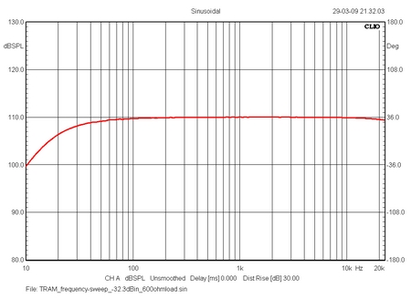 
Left: frequency response from 3.3 uF in place and 620
ohms load.
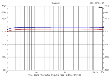
Right: Red = 3.3 uF removed, still 620 ohms load. Blue =
3.3 uF removed and 1.1k load.
So, with the
capacitor removed and a 1.1k load on the
output transformers ( + a new 15 V toroidal
transformer for the regulated 5687 filament
supply) it was time for a new audition with my
Audio Mirror mono blocks driving the DTQWT
speakers. Hum was almost absent from these last
tweaks.
Bass performance didn't appear increased in level
from this, but the midrange certainly got rid of
some minor smearing of detail. Vocals and piano
stood out cleaner, more neutral than before and
well, another step in the right direction. Next I
have to try no load on the output transformers,
that is only the 56k from the Audio Mirror amps.
|
Current schematics:
3.3 uF Obbligato cap removed.
OT load is increased to 1.1k.
12.6 volts regulated filament supply for 5687 tubes
(filaments connected in series)
Building two versions of the 5687 line
stage
The outcome of all above is two versions
of the 5687 line stage. #1 is for my workshop system, and
this will be an integrated version like what has been
running in my main system for a couple of months now. Two
new mains trafos have been ordered with 14 volts outputs
for regulated filament supply for the 5687 tubes. #2 will
be a version with separated power supply for my living
room system. This will have a potted 50 mH choke to make
an overall nice appearance.
So, the line stage was completely
dismantled - takes ½ hour to ruin many hours of work! A
new top panel was made and the whole thing was sanded and
the spray work started all over.
New top panel in place and chassis repainted.
Components shaping up once more.
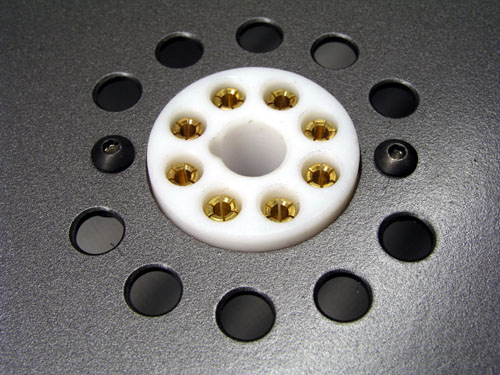
de Luxe WOT
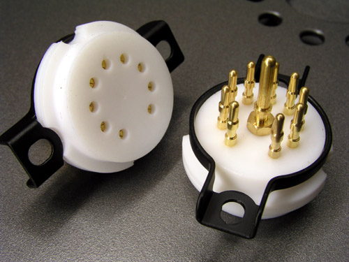 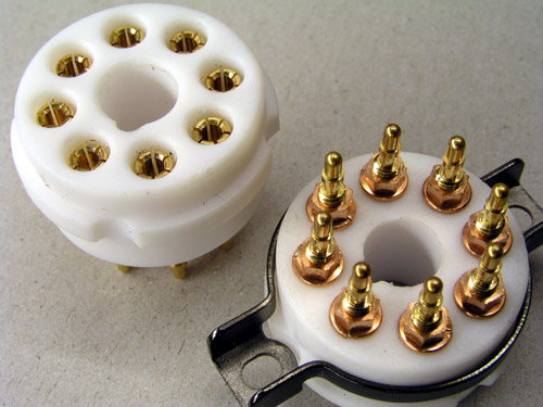
Teflon sockets. These sockets are second to none compared
to any other sockets I've ever tried.
 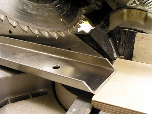
Alu sheets shaping up.
All chassis parts after primer paint.
 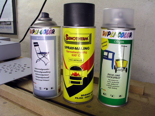
Paints used:
1. Primer spray; quite pricy this one, but good.
2. Spray used for stoves; makes a nice metallic
surface, but rather fragile, thus...
3. Matt acrylic coating.
All of the used spray paints dries
very fast, which is important as I do it outside
and have to keep fingers crossed that no bugs or
any wind born garden debris passes by until it's
safe to take inside.
I never do high-gloss painting as I do not have
the facilities to do so. Takes a serious
dust-free environment.
|
ELMA attenuator
 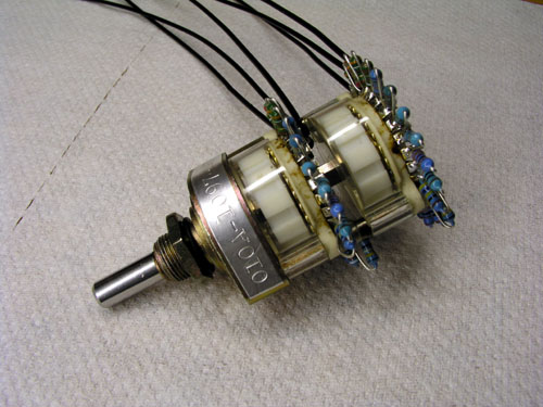
Had an old - but not very much used - 24 step ELMA
attenuator set up for 10k,
so all resistors were removed and a new line for 100k was
bought. A bit messy
after all the soldering, but it works. Plan is to use
this attenuator in TRAM #1.
Every time I have to set up an ELMA
attenuator I have to start thinking how it works, so
here's for my own recollection:
Resistors:
40R2, 23R2, 40R2, 40R2, 60R4, 82R5, 115R, 165R, 232R,
330R, 464R, 649R, 910R, 1k3, 1k82, 2k61, 3k65, 5k23,
7k32, 10k5, 14k7, 20k5, 30k0.
The attenuator starts with a maximum
attenuation of -68 dB and then has 4 steps to -54
dB.
Each additional step is another -3 dB. All in all
better low level control.
Attenuator seen from rear.
Building the 5687 #2, June 09
Paintwork finished and mounting components can begin.
Input selector in place and PSU taking shape.
 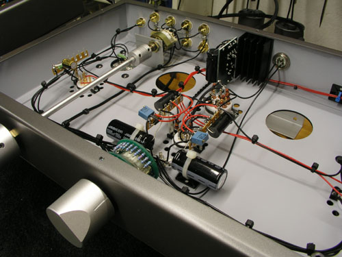
Almost ready for first time turn-on!
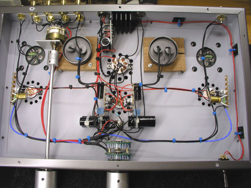
Finally, the 5687 line
stage, version #2 is playing and measuring the
noise level on the CLIO looks satisfying. This
doesn't mean the system is not completely free of
hum as one of the Audio Mirror amps needs an
overhaul, but I'm pleased the 5687 is off the
bench for some time. What's left is making front
panels, led indicators and a relay switch that
allows the preamp to be turned on from the main
unit.
Generally the 5687 WOT is sensitive to nearby
transformers of any kind, so if you need your
preamp to be cramped in with other gear, this may
not be the way to go. But the sound.... the best
I've ever had from any linestage.
|
July 09
The 5687 line stage has
now been playing for a month and a half - I
needed a brake - and a few holidays have been
spent finishing the construction, that is: 12
volt relay that allows me to turn on the amp from
the main chassis (small trafo and relay i upper
right corner of power supply unit). Next the
front panels have been veneered and are ready for
drilling, routing, lacquer, etc.
|
Finished with phones output added!
Read
about other wot line stage projects found on the web.
Return to
intro page.
Aftermath
August
2009
Building amps and speakers is a never
ending story.
I had these comments from Peter Pan:
If you use a capacitor between +B and
tube cathode you must include a small value resistor in
the +B line. This capacitor is basically a bypass
capacitor. If you just parallel up capacitors you end up
with a new multi-resonant network that includes both
capacitors resonances and two new ones. Adding this
resistor serves to “direct” the current at
higher frequencies only into the new capacitor. The value
of this capacitor should be no larger than (or rather
should ideally be) the value of the cathode capacitor
divided by Mu – 1. The series resistor should be no
larger than the anode impedance of valve used at the
operating point used divided by ten. The RC
timeconstant between resistor and capacitor determines
which frequencies are carried by the +B to cathode
capacitor and which will flow through the powersupply and
cathode capacitor (it is basically a highpass). In order
to get the desired results the +B to cathode capacitor
needs to be of significantly higher quality than all the
others. I mean, when using the caps without the
additional resistor. The TRAM omitted this resistor in
the schematic and the build units, as the people making
the kit did not understand it’s function and hence
decided to “improve” the design. The capacitor
value is also not quite right. With 100uF cathode bypass
capacitor and a 5687 operating into a nominal 10k load it
should be around 6.6uF, not 3,3uF.
With the 7119 (E182CC) the gain is higher and the value
is slightly lower. I would use with Ck = 100uF: R = 100R,
C = 4.7…5.6uF. This places the turnover at around
300Hz, which is where I usually place it.
The philosophy behind this approach can be
read from Lynn Olson's lecture on current loops: http://www.nutshellhifi.com/library/ETF.html.
So, 4.7 uF silver/gold cap was inserted between B+ and
5687 cathode. I'm currently running the Amperex 7119
tube, thus 100 ohms and 4.7 uF.
Does it improve the sound? Indeed it does.
Not a giant leap, but a significant improvement. My
system wasn't exactly lacking detail and transparency
before, but in terms of transient quality and harmonic
structure I get a subjectively more true presentation. In
short: It makes listening easier. Thanks, "PP".
Amended schematics below.
The RC-circuit inserted.
Next...
2 x 3V lithium batteries inserted in signal path and
cathode resistor and capacitor removed. RC circuit left
as-is.
When I
had this suggestion from "Peter", I thought
he'd made a typo or something. A battery in series with
the signal? Gotta be kidding!
As
it happens, our/my “ultimate” version of this
concept also uses grid battery biasing (just measure the
voltage across the cathode R – I have no notes left
– and put suitable batteries in series with the
grid, cathode straight to ground. Bypass the battery
stack (Lithium Type Coin Cells is what I use) with a
silver mica cap of at least 10nF and a 4.7 … 22MOhm
resistor.(This is) - not very common because
people believe if it is in series with the grid; it is
“in the signal path” and if it is in series
with the cathode it is not “in the signal
path”. So they stick a big, bad, nonlinear
rechargeable Nicad Battery in the cathode, where it is
exposed to a lot of varying current so this non-linearity
can be injected into the input voltage loop (grid to
“ground”) and amplified and they are pleased as
punch with themselves for having eliminated another evil
capacitor ;-).
Instead they could have placed a nice linear primary cell
(non-rechargable – lithium is best IMNSHO) in series
with the grid, where there is practically no current flow
at all (DC and AC will be in nanoampere region, if any)
and eliminating any battery discharge noise needs a very
small value capacitor...
Keep the 1K Gridstopper as close to the actual gridpin of
the 7119. Obviously, negative pole from the battery to
grid. Consider using lithium button cells, they have very
little added stray capacitance (small size) and will last
many years in this application, the ones for LCD wrist
watches. They do come in 3V so only two in
series….Regards, Peter Pan.
 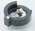
6 V lithium battery stack, 10M resistor and 10nF
silver/mica in place, resistor hidden between components.
Right: These small battery sockets are brilliant and can
be found for both one and two batteries. Makes
implementation very easy.
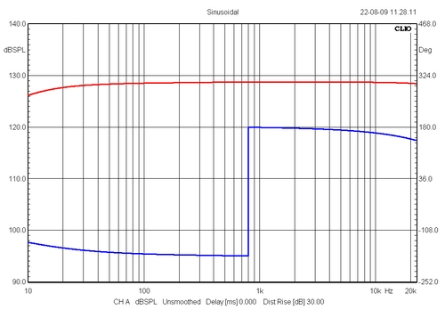
Frequency sweep from battery bias set-up. Blue = phase.
As can be seen, the line stage
inverts phase, thus output transformer inputs can be
swapped or speakers connection reversed.
From cartridge to
speaker, the signal in my system passes 7 valves,
four coupling caps, three transformers, three
interconnects, numerous wires, etc., etc.
Tweakings have to be radical to make a
significant change to the overall sound of the
system, but a system is no better than the
weakest link. One thing I can say: These lithium
batteries are staying!
|
-o-o-0-o-o-
October 2010
6N6P valves for my WOT line stage
I was looking for some 7119 tubes on
eBay when some Russian 6N6P tubes caught my attention (MYCOMPONENT/Ukraine). I bought
eight. For the last year or so, I've been using Amperex
7119 tubes outperforming the 5687 valves - to my ears.
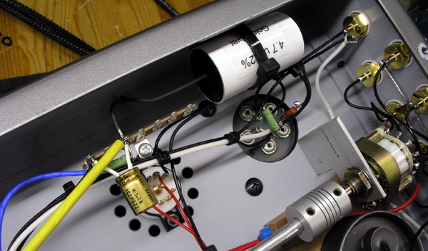
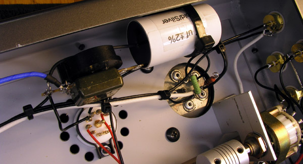
The 6N6P valve is a Russian equivalent to E182CC/5687
except for different pin layout. 6N6P data here.
6N6P takes minor rewiring, but 12V DC filament supply can
stay, connecting both valves' filament in series as was
done for the 7119 tubes. Layout for 7119/5687 heats only
one half the tube, allowing tube swapping and doubling
tube life, which really doesn't matter any more as 6N6P
cost is close to nothing. For 6N6P both triodes are
heated, although only one used for amplification. 6N6P has a screen between the
two triodes, but only using one triode, I didn't make a
ground connection.
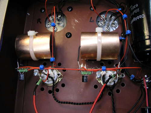
My 5687/7119 wiring
on top. As can be seen, I only heat one half of the tube,
allowing tube swapping and doubling tube life.
Right
out of the box, these 6N6P tubes serves you
another meal compared to 7119. With no changes to the
overall schematics, they appear having slightly less
gain, but no problem with this.
Where 5687 in this set-up may seem a little hard and
bright, 7119 has an expansive, dynamic and maybe an
overly lush sound. Amperex 7119 is truly seductive and
maybe not the most "honest" tube we can find.
6N6P appears very neutral compared to 7119 and soundstage
depth appears excellent, yet at the same time 6N6P seems
to pull everything a little towards the center. Sibilance
is significantly reduced compared to 7119 and high piano
notes appear to die faster. Does the 7119 in reality have
a (serious) problem with microphony? 6N6P tube build
appears rock solid compared to 7119 and I never tried
ring dampers on 7119 to hear what would happen.
After some 20 hours of playing my initial impressions
remain and the tendency to pull the sound stage a little
towards the center seems gone. This is probably the most
neutral sounding valve I have tried yet and it made me go
trough my music collection again, picking out flutes,
piano, violins, etc., instruments with a high content of
overtones and time and again this tube delivers a more
neutral sound without the artificial bloom (smear) from
the other tubes tried. And it does well on female vocals
too...
Re-wiring
my workshop WOT line stage for 6N6P tubes left
the same impression as above. These tubes appear very
neutral and leave even some harsh sounding CDs on the
spinner.
One last important thing I've noticed: When I make a
change and treble level seems to has gone down - and it
really hasn't - then things are moving in the right
direction. Main focus is on the midrange where things
happen - and treble is just something that is there - not
something that attracts attention on its own.
Re-wiring
my friend's TRAM line stage from 5687 to 6N6P
left the same impression. Simply more hifi in the true
sense of the word. My friend's TRAM is driving a 40 wpc
6C33 PP power amp driving a pair of DTQWT speakers.
No need to
say more but this: "Louis, I think this is the
beginning of a beautiful friendship".
29-03-2012. I had this
mail from John Broskie, Tube Cad
Magazine:
Hi,
While searching for 5687 prices, I stumbled on to your webpage that
detailed your efforts with the WOT 7119/5687/6N6P line stage.
Interesting design. Please let me make a few suggestions. The PS reg is
not optimal for several reasons: the 6AS7 is overkill, yet suffers from
low transconductance; the 12AX7 is both current and voltage starved.
Here is how I would do it:
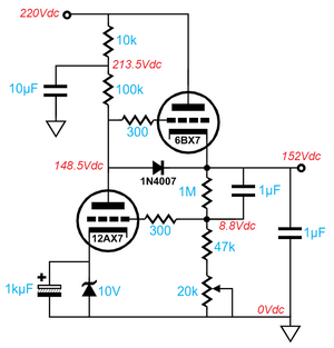
The 6BX7 holds the same pinout as the
6AS7 and draws only 1.5A of heater current (use an Amperex GZ34 or an
RCA 5R4—the small one, not the fat one—rectifier to match the 6BX7
envelope). The 10V zener gives the 12AX7 more plate voltage to play
with and the 10k & 10µF prefilter RC section greatly improves the
performance. The 1N4007 is a protection device for the 6BX7 and it
falls out of the circuit under normal operation. Pots often lose
contact, so the above setup is safer and gives more subtle control over
the output voltage. In SPICE simulations, this regulator circuit gives
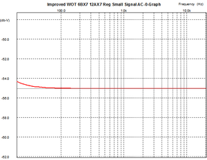
a 12dB greater PSRR (power supply rejection ratio) than the original circuit. The PS PSRR across
frequency graph look good:
By the way, I could not figure out if
the hum you encountered was 50Hz or 100Hz. If the former, then the most
likely source is a ground loop or AC induction; if the latter, then the
PS is to blame. Another by the way, there is an easy alternative
circuit for the line stage amp that would yield a tenfold (-20dB)
decrease in distortion and a huge increase in PSRR, but I have to get
back to work. Regards John Broskie. PS: I plan on reading the rest of your website soon.

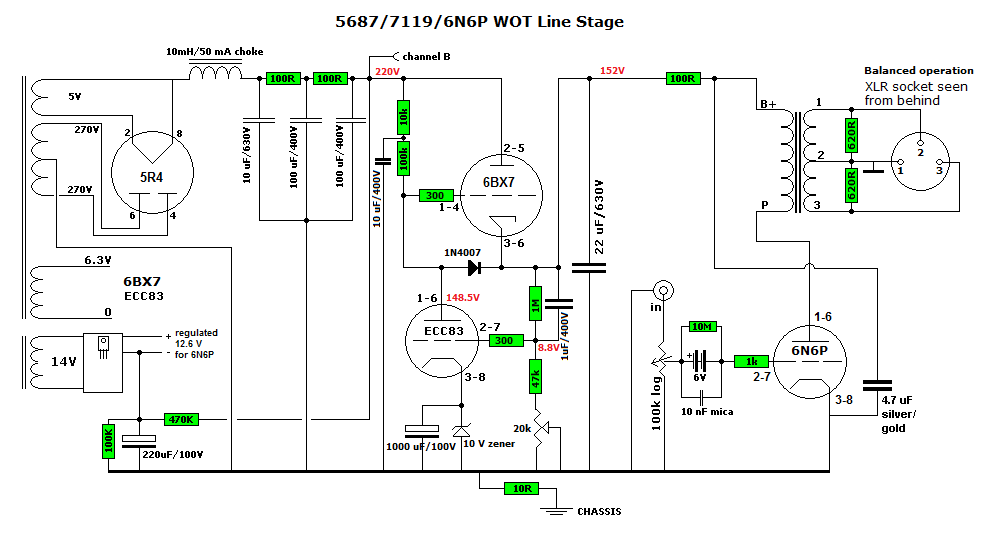
Here the combined schematics.
Thanks to John for taking
the time to respond to my WOT line stage!
I did have some trouble with
the PSU having to swap ECC83 tubes to find one that would draw enough
current to make a stable output voltage. However, no big problem and the
line stage has worked fine for several years now. Nevertheless I have
bought components for implementing John's suggestions and will report
asap.
07-05-2012: Design implemented and it just works excellent. Voltage
levels rock stable and fully adjustable via 20k potentiometer. Highly
recommended should you decide to build the line stage.
I've had a few line stages in for comparison over the years but none
that made me even consider changing this WOT line stage. Even the TRAM2
features capacitor coupling and no matter how good caps we use, caps are
crap and colour sound. They are a necessary evil and whenever possible
we should reduce the number of capacitors directly in the signal path.
This doesn't imply that all the other caps in the design are not a part
of the performance but most likely to a lesser extent. I'm not sure how
important the 10 uF/400 V cap is, probably not a whole lot. For the 1 uF/400
volt I had two spare silver/gold super caps (Jantzen Audio), actually 1
uF/800V, and the 22 uF/800V is Jantzen Superior-Z cap. The 4.7 uF/800V
is a silver/gold Jantzen Audio too. The battery bias may be part of the
good sound too eliminating the electrolytic cap across cathode resistor.
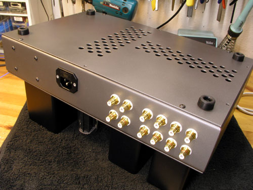
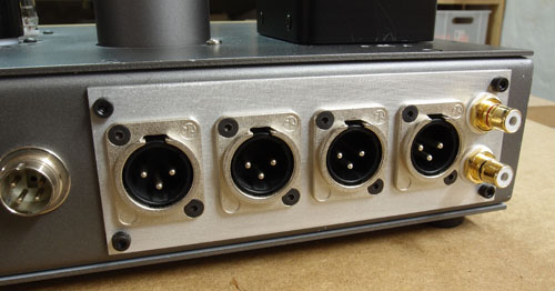
2013: Having the WOT line stage running my
Glowmaster
KT88 and Hypex
amps for bi-amping I needed to add four XLR sockets to the rear panel,
allowing full balanced operation.
When this line stage is finished, it's time to start
building a new chassis! It never ends.
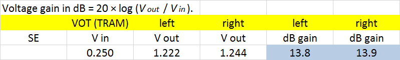
Finally, gain? 14 dB.
|