This study has been on the to-do
list ever since I saw the first Avalon clones
with the middriver stuck into a very narrow and deep
rectangular hole. I always thought the midrange would
suffer congestion but I never had the chance to hear any
of the clones.
As often as possible I
stress the importance of chamfering the driver holes to
allow free ventilation for the rear energy coming from
the driver. Obviously the energy coming from the rear of
the driver is exactly the same as what comes from the
front and as most drivers have very thin and acoustically
transparent membranes we need to do all we can to get rid
of the rear energy in order not to have that energy being
reflected back towards the membrane. The reflected rear
energy will be delayed and hitting the membrane it will
cause smearing of detail and increased (subjective)
distortion.
Further more a short "transmission line" behind the
driver may seriously impair the flow of air and alter frequency response
as seen below. It may not always show up clearly on impedance plots, but
impedance and frequency response should be checked before proceeding to
any crossover simulation.
Before we go to the study below,
here's a scary example of a ScanSpeak 15M midrange driver:
A
client brought in a nice pair of cabinets with fronts chamfered like
Ellam-FLEX and to the left a straight driver hole of ~48 mm. Below is
seen what happens. Red graph is as-is and green after chamfering the
hole with a chisel and hammer. Not nice but effective. The red graph
made it almost impossible to produce a decent crossover without dips and
peaks here and there. After chamfering; piece of cake. I hope this
clearly demonstrates how bad it can go when neglecting this important
issue.
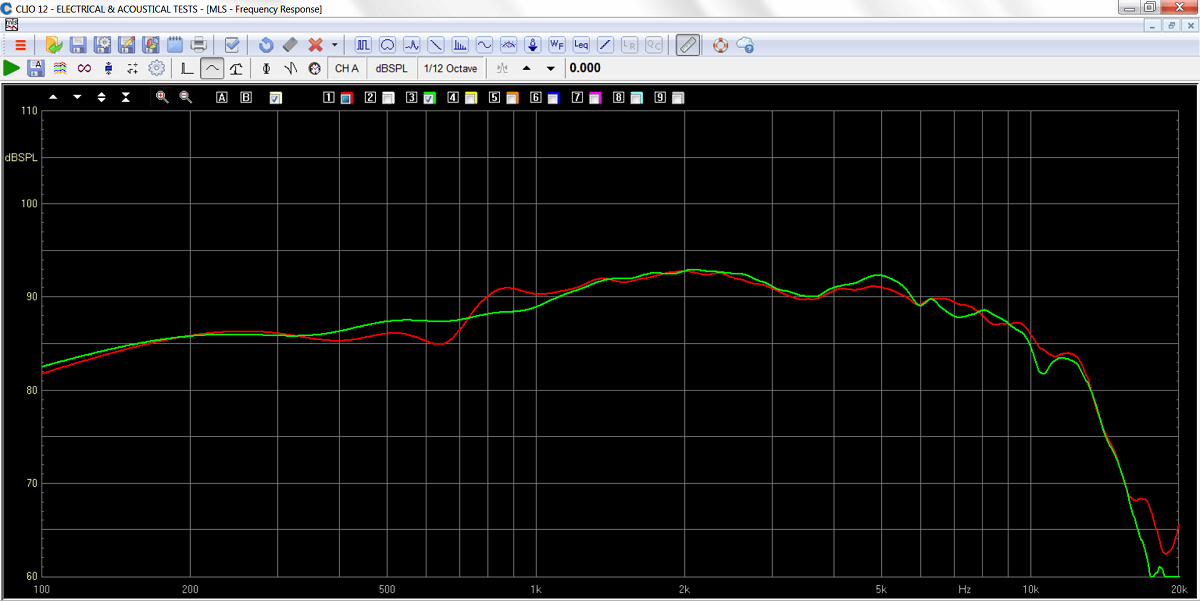
Red = straight driver hole. Green = driver hole chamfered ~45 deg up to
around 15 mm from driver rebate.
Set-up:
33 liter test cabinet with lots of damping
material (MDM3).
Front panel = 30 x 50 cm.
Driver placed on center, 20 cm from top.
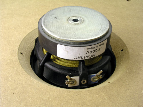
Driver: SEAS CA12RC, flush mounted.
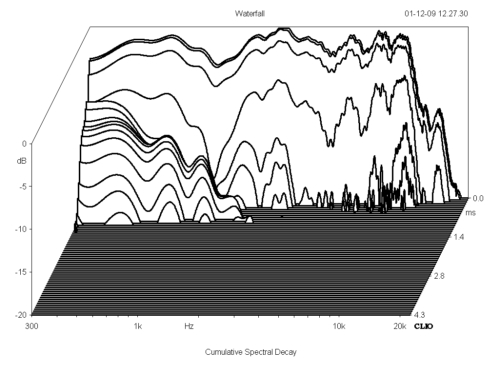
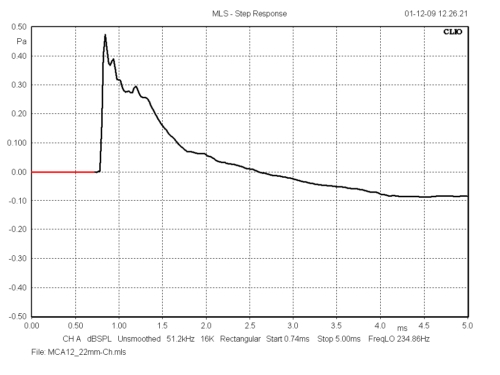
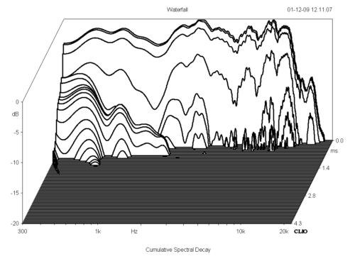
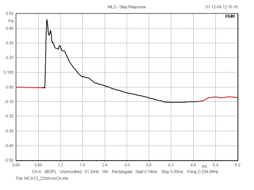
I was sure
the
differences would show up on CSD (cumulative spectral
decay) and step response, but it didn't. Much to my
surprise! But what surprised me even more was that it had
a significant impact on frequency response. What I
already knew from mounting a small middriver into a
narrow tube (A) was the impact on sound (TJL3W and
Classic 3-Way). Comparing A and C on pink noise leave no
doubt of the importance of chamfering driver holes. On C
we hear a full-bodied sound with deep and wide low-end
response where A will make the sound thin with an
unpleasant presence. It sounds congested.
The various scenarios. D and E were not tested after
having tested A-B-C.
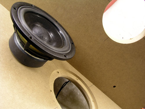 
Left: Two 22 mm MDF sheets were used for study. Right: 22
mm/no chamfering.
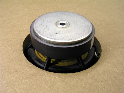
Left: 22 mm/45 deg. chamfering. Right: 44 mm/no
chamfering.
 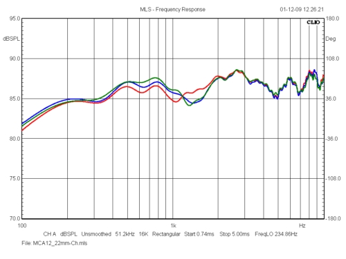
Frequency response from A red), B (blue) and C (green).
Right: 5 dB scaling 100-10000 Hz.
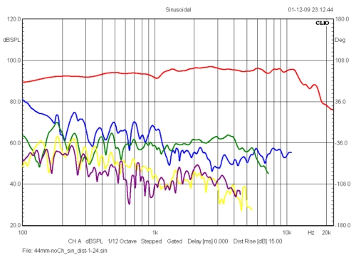 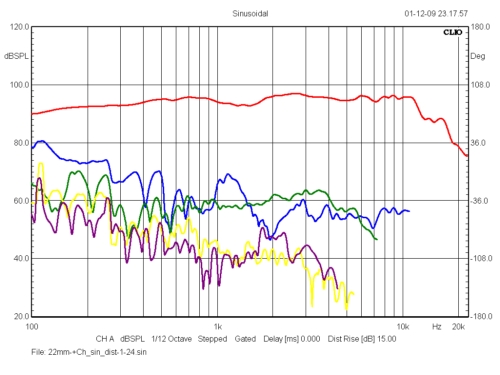
Left: Distortion from situation A. Right: Distortion from
situation C. Distortion raised 15 dB. No apparent
differences.
Blue = 2nd harm., green = 3rd harm., yellow = 4th harm.,
purple = 5th harm.
22 mm front panel without chamfering.
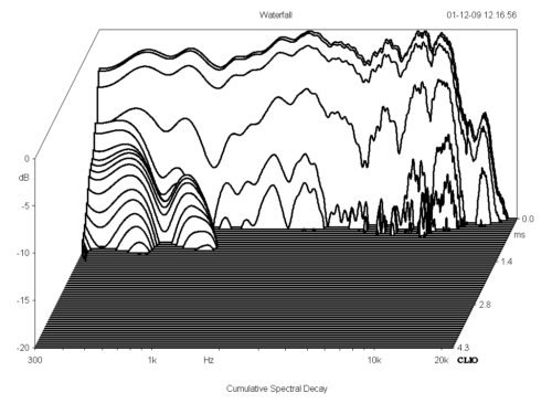
22 mm front panel with chamfering.
44 mm front panel without chamfering.
Worst
case
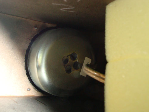
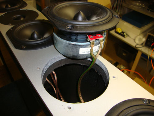
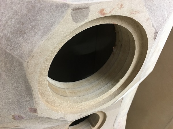
This is the worst example I've seen from
a commercial speaker, System Audio 1750.
Due to the thick front panel and magnetic shield these drivers
certainly can't breathe. Hardly optimal.
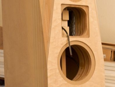
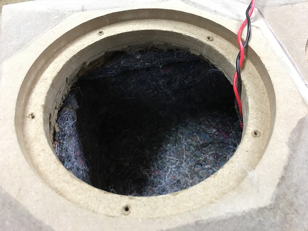
Here's an even worse example. I hope this ~4"
transmission line is part of the equation.
|