 |
Fig.
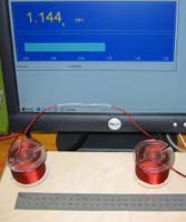
1. Coils 20 cm apart: 1.14 mH |
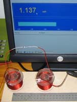 |
Fig.
2. Coils 10 cm apart: 1.14 mH |
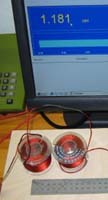 |
Fig.
3. Coils as close as possible: 1.11 mH |
|
Fig.
4. Coils placed close as seen on picture, one coil turned
upside down: 1.18 mH Compare with fig. 3. |
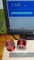 |
Fig.
5. Coils placed close as seen on picture: 1.15 mH This is OK. |
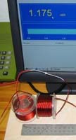 |
Fig.
6. Coils placed close as seen on picture: 1.18 mH Don't do this. |
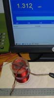 |
Fig.
7. Coils placed on top on one another, same orientation: 1.31 mH Never do this. |
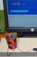 |
Fig.
8. Coils placed on top on one another, reverse
orientation: 1.02 mH Never do this. |
Coils placed close to
aluminium |
|
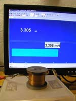 |
Fig.
9. 3.3 mH cored coil, vertical orientation. Coil on plastic surface: 3.31 mH |
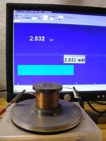 |
Fig.
10. 3.3 mH cored coil, vertical orientation. Coil on 15 mm alu: 2.83 mH |
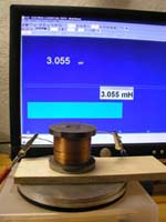 |
Fig.
11. 3.3 mH cored coil, vertical orientation. Coil on 15 mm alu + 10 mm plywood: 3.06 mH |
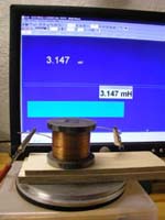 |
Fig.
12. 3.3 mH cored coil, vertical orientation. Coil on 15 mm alu + 15 mm plywood: 3.15 mH |
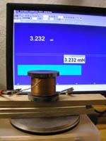 |
Fig.
13. 3.3 mH cored coil, vertical orientation. Coil on 15 mm alu + 25 mm plywood: 3.23 mH |
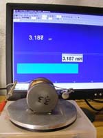 |
Fig.
14. 3.3 mH cored coil, horizontal orientation. Coil on 15 mm alu: 3.19 mH |
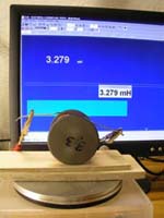 |
Fig.
15. 3.3 mH cored coil, horizontal orientation. Coil on 15 mm alu + 15 mm plywood: 3.28 mH |
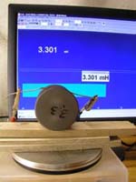 |
Fig.
16. 3.3 mH cored coil, horizontal orientation. Coil on 15 mm alu + 25 mm plywood: 3.30 mH |
|
Conclusion
to this small additional study: Coils placed vertically near to aluminium display a significant reduction in inductivity. Coils should at least be 5 cm/2 inches from nearest aluminium surface. More is recommended. Coils placed horizontally near to aluminium display only minor impact on inductivity, however 3-4 cm distance is recommended. |
|
How about caps? |
|
|
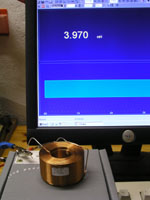
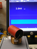
3.9 mH
air cored coil Measures 3.97 mH |
|
Obbligato
cap in copper tube: Very little impact when placed besides the coil. |
|
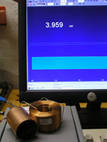
Obbligato
cap in copper tube: Reduction in inductance when placed directly in the electromagnetic field of the coil. |
|
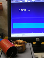
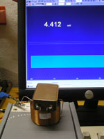
Capacitor
in alu tube: Little impact when placed aside coil. |
|
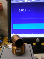
Capacitor
in alu tube: Reduction in inductance when placed directly in the electromagnetic field of the coil. |
|
Silver
mica cap in metal (Fe) housing: Fortunately we never use these for crossovers. |
| All other caps in non-metal wrap had no impact on inductance. | |