Graphite Resistors Make your own non-inductive graphite resistors Wikipedia: The mineral graphite is one of the allotropes of carbon. It was named by Abraham Gottlob Werner in 1789 from the Greek ãñáöåéí (graphein): "to draw/write", for its use in pencils, where it is commonly called lead, as distinguished from the actual metallic element lead. Unlike diamond (another carbon allotrope), graphite is an electrical conductor, a semimetal, and can be used, for instance, in the electrodes of an arc lamp. Graphite holds the distinction of being the most stable form of carbon under standard conditions. Therefore, it is used in thermochemistry as the standard state for defining the heat of formation of carbon compounds. Graphite may be considered the highest grade of coal, just above anthracite and alternatively called meta-anthracite, although it is not normally used as fuel because it is hard to ignite. Let me say already here: I do not find any sonic difference in performance from wire wound, graphite, MOX, Duelund and film resistors tested on my Jenzen D (diamond tweeter). The differences they may display in induction is infinitesimal and cannot count for any sonic difference. Their difference in resistance vs. temperature may vary and should be considered where high levels of current is passing. Buying seriously expensive resistors is a waste of money - to my experience. Clean woodoo. The problem here is that when we buy something expensive, it just got to be better. The special feature of a graphite resistor, except for being non-inductive, is that it displays a negative temperature coefficient (a = -0.5*10^-3, (1/°C), thus when the voice coil heats up - and increase impedance - the graphite resistor will counteract this by lowering impedance. In practice this is most likely rubbish as the graphite resistor would have to act as an exact mirror of what is going on in the voice coil. This is a very unlikely scenario, but that's how the story goes and as always, no measurements have ever - to my knowledge - been published that supports the claim. Voice coils come in all forms with regard to former (alu, kapton, etc.), wire material, wire diameter and length, and to claim that any graphite resistor in front of this will "read" the voice coil and counteract fluctuations in impedance is obviously nonsense. I many cases the attenuation resistor(s) is/are not directly in front of the driver, rather in front of the crossover components, thus the crossover still sees a fluctuating impedance and we're nowhere. If we have a problem with over-heated voice coils, we should build bigger speakers. Nevertheless, it is
claimed that graphite resistors sound better compared to
MOX or wire-wound, and if a graphite resistor will make
you happy you should go for it, as it can be made for
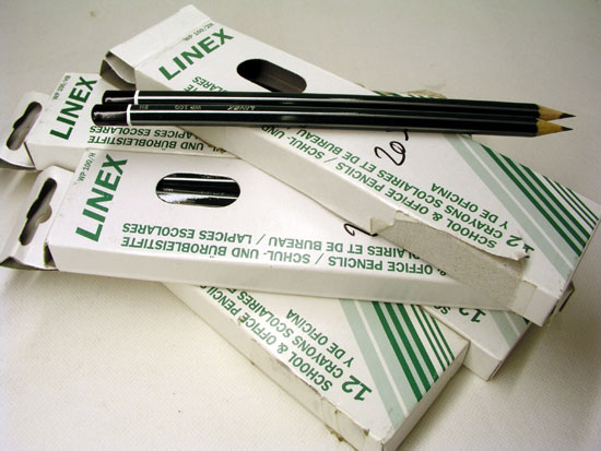
nothing from the graphite rod found in any standard
pencil. We only need to know the grades of pencils to
buy.
Conversion of grades from UK to US looks like this: B = #1, HB = #2, F = #2½, H = #3 and 2H = #4 (Wikipedia again).
My pencils are 175 mm long
and the first thing to do is to find out what's the
resistance of the full-length graphite rod, thus the wood
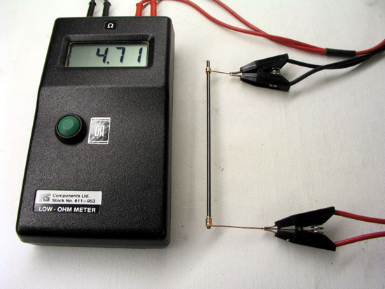
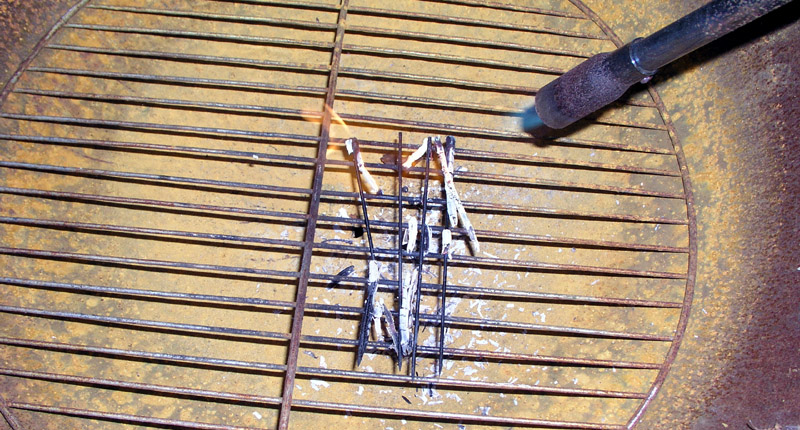
was removed at the upper end and resistance measured: Resistivity of pure graphite is 1380 * 10^-8 ohms/m/m^2, that is 0.0000138 ohm/meter. Now, 1 square meter of graphite is quite a lot, actually 1,000,000 mm^2, thus 1 mm^2 is 13.8 ohm/meter. The rod here being 2.2 mm diameter have a square area of 3.46 mm^2. So, one meter of pure graphite pencil should have a resistance of 3.99 ohms and a 17.5 cm pencil 0.7 ohms. Actually they're not, rather 6-25 ohms, thus some clay has been mixed in. How much we don't know and this is probably a secret for every pencil manufacturer and who cares? Fortunately an amount of clay has been added that provides us with something useful for crossover resistors with regard to physical length. The grades of hardness are made by mixing the graphite with various amounts of clay powder. Next the rods are dipped in wax or oil to provide smoother writing. The latter we have to get rid of to make a proper termination and you may boil your graphite rods is caustic soda or simply burn the ends as seen below. I use our weed burner and it only takes a few seconds to heat the graphite until it glows. No wax or oil will be left after this! Before you rush to your local pencil supplier, there's one important thing you need to make proper resistors: A low-ohm meter! These definitely do not come cheap, so in the end it may be cheaper to buy the commercially available graphite resistors. I paid ~400 USD for my meter. A standard meter may be used but make sure you have 1% resistors at hand as controls. Thanks to Max, here's a link to a supplier (California) of pencil leads: http://www.jetpens.com/index.php/cPath/99 Another link here from Mark, http://www.suppliesnet.com/, (Louisiana, US) search for "leads" and you can find from 3B to 6H. The soft range will be interesting for low-ohm resistors as the leads I have will make quite short resistors for e.g. 0R47, 1R0, etc.
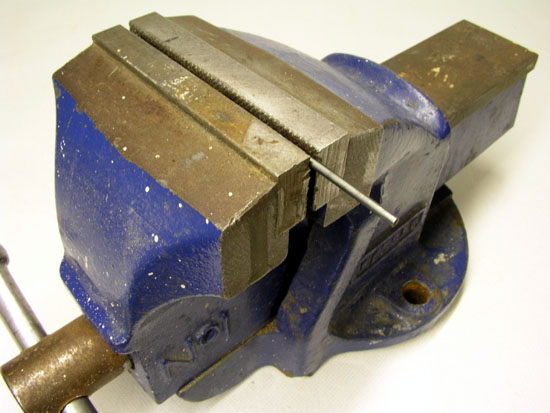
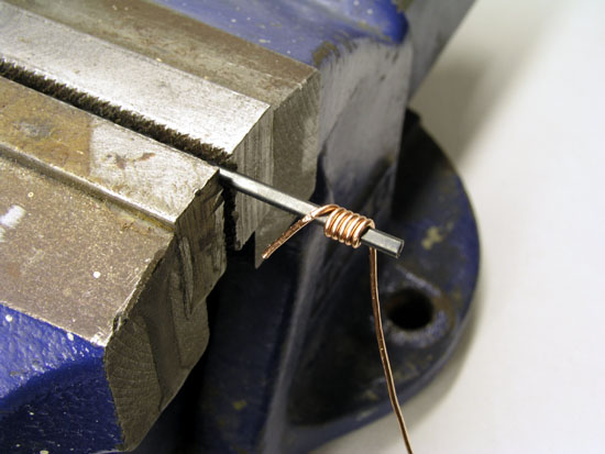
The pencil graphite rod is exactly 2.2 mm in diameter, and you need a 2.1 mm drill fixed in a vise as seen above. And I'm serious here. Not 2.2 or 2.0 mm but 2.1 mm. The reason for this is that you have to twist 0.8 mm copper wire 5 times around this 2.1 mm drill, making it a fraction smaller than the 2.2 mm graphite rod. This way you can screw the copper wire onto the graphite rod (counter-clock) and it stays tight. The copper wire has to be 0.8 mm, not 0.7 or 0.9 mm. I've tried a lot of wires - and 0.8 mm copper wire just works. You may use silver wire, but will have to find out the optimum diameter as silver is softer compared to copper and may work differently. And by the way: There will - usually - be loads of copper wire in your crossover components so to use silver here wire is only show-off. To do some further experiments
I needed more 0.8 mm copper wire and it turned out my
local wire pusher was out on 0.8 mm wire. We searched
countless shelves for some 0.8 mm wire, even the multi-strand installation cables. No 0.8 mm left could be
found.
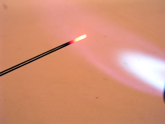
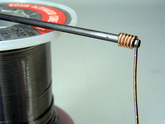
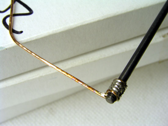
Next you need to remove the wax/oil from the graphite rods and as mentioned earlier, a weed burner works excellent. And DO NOT put your finger on a newly burned graphite rod. It's hot like hell and will burn you to your bones! Right photo: Copper wire screwed onto graphite rod.
Next you need to find out the length of the graphite rod to produce the desired resistance. Cut the rod at some 5 mm extra and repeat heat treatment. Right photo: Solder the first copper termination and heat it for a considerable length of time until the solder has fully penetrated all windings. This way a small amount of solder will go below the windings as the copper will expand during heating and once cooled - and shrunken, the termination will stay rock-solid and you shouldn't be able to pull it off without damaging the graphite. At least I can't. I have had the opportunity to check one commercial graphite resistor and can say that the termination shown here is just as good if not even better. Finally add the second termination and keep screwing until you reach target resistance and solder.
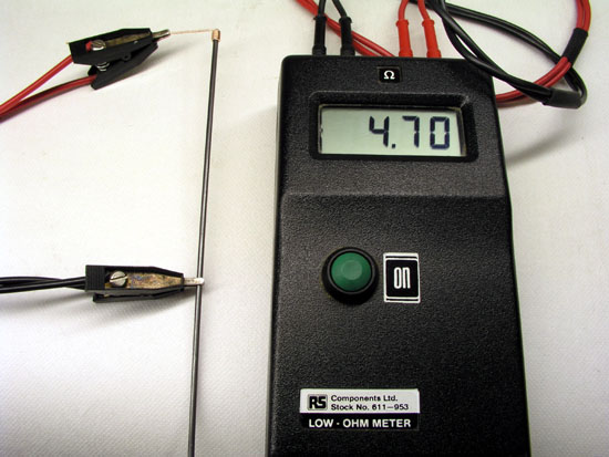
Left photo: Check
resistance and cut off excessive graphite. Right photo: I
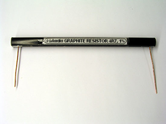
also happen to have some pertinax tubes and they work
excellent for housing the fragile graphite rods. Slice
the tube at both ends and push the terminated graphite
rod through and pull out the wires. Seal one end with
Superfix or similar and fill the tube with fine dry sand
for cooling. Seal with Superfix and you're done! So, what's the watt rating of our homemade graphite resistors? Hard to tell, but at least it should do until the solder melts and I'll complete the study with some tests asap. There's a good reason for the high price on commercially available graphite resistors. The development phase was great fun, but once you've made a few, it becomes boring and I would definitely charge you at least 20 USD for a resistor. And please do not ask, because I don't make these to order. Appendix I
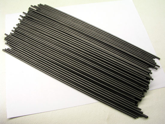
Burning pencils takes a little practice: The hard graphite, from HB to 2H is brittle and will fracture if subjected to uneven heat. Place the pencils on your garden grill with 1 cm apart. Heat gently until the wood catch fire and apply only as much heat as necessary to keep burning. Once the wood is gone, let it cool and clean the graphite rods with steel wool and heat the ends as shown above to prepare for termination. Appendix II
Above the resistance of a HB rod
vs. temperature. The graphite was cut at ~15 ohms
and terminated with teflon wires to allow the resistor to
be placed in our kitchen owen. Temperature was checked
with a thermometer and we're doing +/- 3 ºC of target.
Not bad for a kitchen owen! What we see is a nice linear
decline in resistance vs. temperature. An increase in
temperature of 230 ºC will lower the resistance ~18%.
The resistance was not corrected for the increase in
resistance of the teflon wires used for measurements as
these are close to zero, thus will only have a minor
impact on results. Heating MOX and sand-cast wire-wound (Monacor) resistors with a heat gun to around 200 ºC clearly shows these resistors do not change noticeable. The MOX not at all, and the wire wound maybe 1% (negative) change vs. temperature, so if you have some resistors in front of your e.g. middriver crossover taking some serious heat, use MOX. These will be better keeping sound level stable. |