Vent tuning of ported systems
Copyright 2005-22 © Troels Gravesen
The
following study is only related to port tuning.
I hope to have time to dig a little more into optimum box
volume and optimum tuning frequency for ported systems in
future studies.
I rush have to say that thick books and papers have been
written on these subjects and I'm not going to solve the
problem of vent tuning here. We very soon run into heavy
math and as most drivers are very un-linear mechanical
devices, they don't follow rules. So, from a practical
viewpoint I'm going to test some of the formulas
available for calculating vent dimension and show you my
measurements.
A number of people have
commented that my recommendations for vent dimensions do
not meet their calculated values - and no wonder, read
on...
In all the ported systems
I have made, I have used box simulation programs
suggesting optimum cabinet volume (Vb) and vent tuning
(Fb). However, port calculations have never been in
accordance with real world measurements. Usually the port
has to be shorter than predicted. In the following study
I have used the formulas available at:
http://www.diysubwoofers.org
This is an excellent site with a wide range of
information related to box calculations. And here you can
find the following information regarding port
calculation:
Port
Length
The port length required to tune a volume of air to a
specific frequency can be calculated by using the
following equation: Lv =
(23562.5*Dv^2*Np/(Fb^2*Vb))-(k*Dv), where:
Dv = port diameter (cm)
Fb = tuning frequency (Hz)
Vb = net volume (litres)
Lv = length of each port (cm)
Np = number of ports
k = end correction (normally 0.732)
The value for k, the end correction, can be fine-tuned by
using the following values to derive the appropriate end
correction figure for each end of the port, then adding
them together
Both ends flanged: k = 0.425 + 0.425 = 0.850
One end flanged, one end free: k = 0.425 + 0.307 = 0.732
Both ends free: k = 0.307 + 0.307 = 0.614
Normally, k=0.732 is assumed.
So, the tricky part here is the value of k
being dependent on the vent ends being flared or not.
This site does not specify what size the flaring must
have in order to be regarded a flange. Nor does it
specify any damping material or the impact on measuring
performance from this. Thus, in order to have both ends
flared I have made a flange from a 25 x 25 cm panel and I
have made initial measurements with and without damping
material.
Before we get to actual measurements, here's the set-up:
A 29.5 litre box was constructed and a number of vents
were cut from 72 mm (internal diameter) PVC tubing: 10,
15, 20, 25 and 30 cm lengths were chosen for
measurements.
The CLIO was set at +12 dB output and drivers were driven
directly from the CLIO board.
Vent tuning is only related to the mass of the air in the
box and vent and the dimension of the vent has nothing to
do with the driver and in practical terms any driver can
be used for these experiments, but don't use a tiny
4" driver for a 29.5 litre enclosure.
I'll demonstrate what happens to the Scan-Speak
21W/8555-01 bass driver from applying various vents as
depicted below.
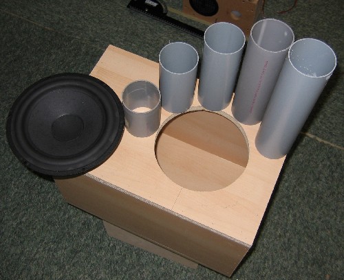
Fig.
1. 29.5 litre box, 8" driver and 5 vents of
different length.
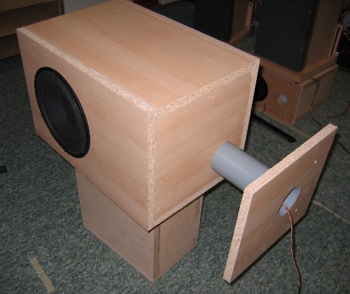
Fig.
2. Vents were attached to the box to have one end flared
by the internal
panel of the box and an additional flange could be added
by the shown panel.
Fig.
3. "Flanged" is when the vent end is
"sharp",
"flaring" is when the vent end is chamfered
e.g. 45 deg. or rounded.
Driver tested with various vent
lengths.
Fig.
4. 29.5 litre box with no damping material.
Vents: red = 300 mm, blue = 250 mm, green = 200 mm,
yellow = 150, purple = 100 mm.
As can be seen, a very high tuning frequency from this
un-damped
box creates a spurious peak around 50 Hz.

Fig.
5. 29.5 litre box including damping material.
Vents: red = 300 mm, blue = 250 mm, green = 200 mm,
yellow = 150, purple = 100 mm.
(4 sheets; 30x60x3 cm mixture of sheep's wool and
polyester were placed on internal surfaces of the box)
Adding damping material to the cabinet
decrease the vent tuning by creating a "larger"
cabinet. No surprise here either, all in accordance with
expectations.
Results, damped box:
Fig.
6. The table shows the tuning frequencies from the chosen
vent lengths
compared to the calculated lengths with the k
value set at 0.732.
As can be seen, there's a major discrepancy between
measured
and calculated values and the vent has to be much shorter
than predicted.
Results, un-damped box:
Fig.
7. The table shows the tuning frequencies from the chosen
vent lengths compared to the calculated lengths with the
k value set at 0.732.
As can be seen, the difference between actual and
calculated vent length has diminished.
Vent flange - does it have an
impact on Fb?
The results from the un-damped box and k =
0.732 should fit for a port flanged at one end as has
been performed. So, apparently something is wrong. It has
to be said that the difference between a double-flanged
vent and two free ends was less than 0.6 Hz, so when the
vent is - at least - sharply flanged this does not make a
whole lot of difference.
As the vent is placed outside the box it does not change
the volume of the box. The driver may count for a minor
volume and the suggestion that you place the driver in a
plastic bag and submerge it in water to measure the
volume is a little funny. I wouldn't do it, and as a lot
the "driver" is actually air, it wouldn't be
correct either. Even if the driver would count for 1
litre volume, this would only have minor impact on the
calculations. 1 litre = 3.3% of the total volume.
Insignificant.

Fig.
8. Flanged vent: Red = no flange, blue = flaged at one
end, green = flanged at both ends,
yellow = flanged of one end - but vent inserted into
cabinet (normal position).
Tuning frequency vs. flanging:
No flange: 34.6 Hz
One end flanged: 33.9 Hz
Both ends flanged: 33.7 Hz.
Well, not much to write home about from this study! From
no flange to double flange we lower the vent tuning by
0.9 Hz.
Most softwares - to my knowledge - are
well in accordance when it comes to calculating vent
dimensions and in some cases even damping material can be
included (JBL software, e.g. no damping, minimal damping,
normal damping (whatever that is...) and heavy damping.
The JBL software is in accordance with the calculation
based on the formula shown at
www.diysubwoofers.org.
Example: Vb = 29.5, Fb = 28.7, vent diameter = 7.2 cm.
1. JBL: vent = 7.2 (ID) x 46.79 cm with no damping.
2. "diysubwoofers": 7.2 x 45.00 (with k =
0.732).
Even with heavy damping the JBL software predict a vent
of 7.2 x 37.79 cm, where the actual measurement says 30
cm.
Damping material:
Vb = 29.5 litre
Scan-Speak 8" bass driver.
vent: 72 (ID) x 200 mm

Fig. 9. Impedance of bass driver with no
damping (blue) and heavy damping (red).
Heavy damping here means 10 mm polyester foam on all
internal panels and 2 sheets of Monacor MDM-3
added - and not blocking the passage to the vent!
The MDM-3 is a great material consisting of 2/3 sheeps'
wool and 1/3 polyester fibre.
As can be seen, the addition of damping
material has a significant impact on the impedance
profile and the vent tuning is lowered from 37 Hz (no
damping) to 33 Hz (heavy damping) and no surprise here.
Again damping material increases the virtual volume of
the cabinet and has to be taken into account when
deciding Fb and vent length.

Fig.
10. Fb vs. amount of damping material:
Blue = no damping, purple = 1 sheet of MDM-3, green = 2
sheets of MDM-3,
red = 10 mm polyester foam + 2 sheets MDM-3.
Signal input:

Fig. 11. Impact of signal input on vent
tuning.
Speaker driven directly from CLIO board at red:
+12 dB, blue = 0 dB, green = -10 dB, purple = -20 dB.
Obviously Fb is unaffected by the signal
input, whereas the height of the impedance peaks
decreases with increasing voltage. It may indicate that
even the 72 mm vent is too small for high signal levels.
Fig.
12. Nearfield SPL measurement at different input levels.
The speaker is here driven from a power amplifier between
the CLIO and the speaker. Setting the output level to -20
dB normally produces a signal level around 80-90 dB at 1
meter distance - depending on the sensitivity of the
driver. The dip in response between 30 and 40 Hz is due
to the vent being in resonance with the drivers, thus
damping the cone movement. Interestingly the Fb decreases
with increasing signal applied to the driver. The CLIO
output was set at: red = -30 dB, blue = -20 dB, green =
-10 dB, purple = 0 dB (YES, I'm using ear protection!)

Fig.13.
2.2 mH coils of different resistance inserted between
CLIO and driver.
Red = No coil, purple = 0.16 ohm cored coil (Monacor),
green = 0.47 ohm (Mundorf),
blue = 1.09 ohm (small Intertechnik coil, cored and 0.6
mm wire).
Obviously the coils with higher resistance display higher
overall impedance,
otherwise only minor difference.
Flaring of vent:
This will be the last addition to this
page: Impact on Fb from flaring the vent. The data were
collected during fine-tuning of the
SP38/13
construction:
The Fb for the SP38/13 construction was
targeted at 33-35 Hz and a vent of approx. 20 cm length
was from practical experience found to be suitable.
When inserting the vent the Fb was measured from three
different scenarios:
1. Inner end was free and outer end was flanged.
2. Inner end free and outer end flanged and flared.
3. Inner end flanged + flared and outer end flanged and
flared (see fig. 3).

Fig. 14. SP38/13 vent tuning.
The reading here is blown up to view the
minor changes from this exercise: Red =
one end free, outer end flanged (sharp). Blue
= one end free, outer end flanges and flared. As can be
seen flaring the vent opening rises the Fb slightly,
approx. 1-1½ Hz, apparently reducing the vent length
slightly. Green = both end flanged and
flared. This adds some 10 mm to the total vent length and
lowers the Fb approx. 1 Hz. Not much. The router bit used
for flaring the vent has a radius of 13 mm.
 
Flanged vent to the left. Flanged and flared vent to the
right.
As can be seen from this SP38 work, not a
whole lot is happening from flanging and flaring the
vent. This does not imply that flaring the vent is not
worthwhile. Rounding the edges significantly reduces vent
noise when a large amount of bass is reproduced, and
well...looks nicer I think.
From this vent-tuning study is can be seen
that calculating the vent dimensions is tricky business.
From practical experience I have learned to multiply the
vent length by 0.6-0,7 to get the targeted Fb. Quite some
deviation from all the nice math. So, no clear
recommendation but get help from someone with measuring
equipment if you want it right.
15-01-2006:
Some time ago I had a mail from Bjorn Johannesen telling
me about the acoustic impedance at the vent opening.
Bjorn has written an excellent article on Martin J. King
for Dummies, look here:
http://www.t-linespeakers.org/design/MJK-for-dummies/index.html
Bjorn states:
Effective Length versus Physical Length -- At the
opening, there is an acoustic impedance which makes the
line behave as if it were slightly longer than the
physical line at low frequencies. MathCad includes this
impedance so depending on the geometry of your cabinet
the actual tuning frequency might be a little lower than
you would expect.
Thanks to Bjorn for his comments.
If this goes for TLs, it's a likely explanation for bass
reflex designs as well and should explain the discrepancy
between calculated and actual vent length.
|