|
Vifa C17-II, Monacor
DT300+waveguide
Copyright
2010 © Troels Gravesen
CROSSOVER
TWEETER
MODS MEASUREMENTS
Go to C17-I
Go to C17-III
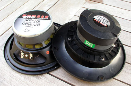 
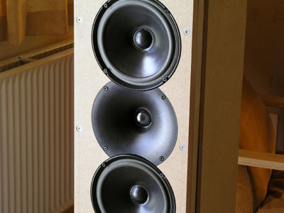
Monacor SPH176 midbass and DT300 +
waveguide. The SP176 is an interesting driver with a
vented, stamped metal
chassis but some other time. Here we stay with the Vifa
C17.
The waveguide needs 4 pcs. 4 x 12 mm standard metric
screws to be held in place. They don't follow the kit.
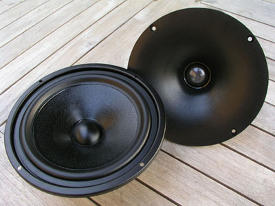
I've been looking
at the Monacor DT300 tweeter for some
time and finally decided to buy a pair. This is a
30 mm soft dome and how would this driver perform
compared to my much loved ScanSpeak D3806/8200
tweeter? The latter has a 38 mm voice coil and
really needs a supertweeter to make it up to 20
kHz.
The DT300 may be a
suitable compromise for two-way systems
providing a possible low point of crossover.
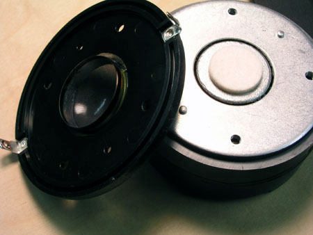
What's even more interesting is a new waveguide
made especially for the DT300 tweeter. This very
short plastic horn increases sensitivity by some
6 dB at 2 kHz and a very simple 1st order
crossover is possible with the Vifa C17 drivers.
I never thought I'd make a 1st order crossover
work properly, but this tweeter seems to make it
possible, helped by the gentle roll-off from the
C17 drivers.
It may be difficult
to distinguish between a horn and a waveguide,
but usually a horn takes a compression driver and
a longer horn, where a waveguide in principle can
be applied to any driver (think of PA bass
speakers), from small domes to large cones. A
waveguide is usually a very short and shallow
horn, in this case only some 40 mm deep.
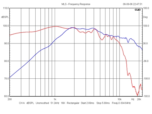
Individual response of
drivers. With the waveguide in front of the dome,
the sensitivity is raised to 100 dB/2.8 V at 2
kHz and the tweeter can be equalised by a very
small capacitor, e.g. 2.7 uF to flatten the
response. This also means that distortion may be
significantly reduced in the crossover region as
the dome really doesn't move much due to the
acoustic amplification from the horn. 2.7 uF in
series and a LCR circuit to flatten the driver's
impedance is all that's needed to make a point of
crossover around 2.5 kHz.
|
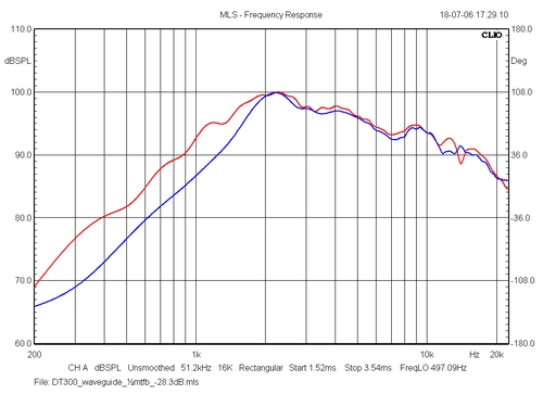
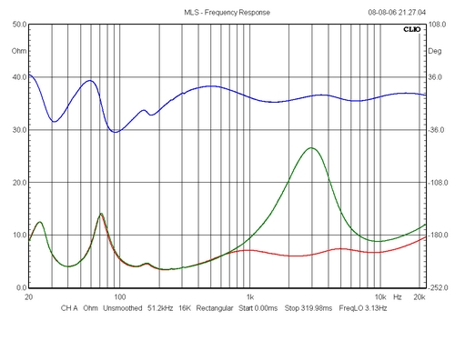
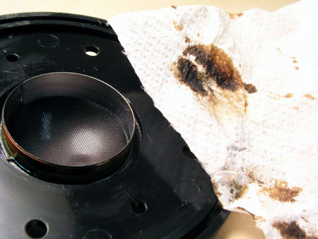
What's seen above is what
happens if the magnetic oil is removed from the
tweeter. Actually I've never seen a tweeter
"submerged" in magnetic oil like this
one. There was oil all over the place, the pole
piece being covered with this magnetic sauce.
Removing the oil increases response down towards
1 kHz, making the crossover construction much
easier. I'll skip the details but running the
LspCAD on the un-modified tweeter wasn't that
easy.
The red graph was from before the tweeter mods
were fully completed.
|
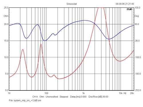
Above the impedance
profile of tweeter after removing the magnetic
oil (red) + mods.
The DT300 needs a lot of burn-in. Not what I
usually find on tweeters, but this one seems to
be the exception.
|
Routing new front panels for the C17 and
DT300/waveguide drivers.
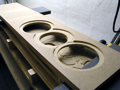 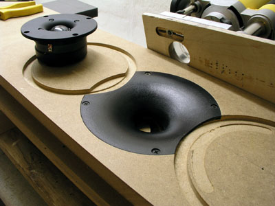
To
get the drivers as close as possible it's necessary to do
the routing as seen on these photos. The position of the
drivers
is shown on the drawing below. I was afraid the waveguide
was made from some brittle plastic that would fracture
from the router
but I was able to route very slowly into the plastic
without trouble. The plastic turns a bit hot and starts
melting, but take it easy and
only do a fraction of a millimetre at a time. The
waveguids are cheap - less than 10 US $) so don't panic
if you break one.
If you have a router with variable speed you may try
running at low rpm. My router hasn't.

Router
plan for the drivers.
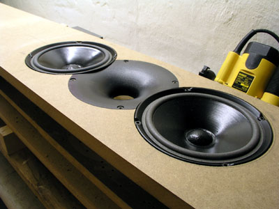
What I also did this time was lifting the vent to be
completely symmetrical to
the two Vifa drivers. I used a Monacor MBR75 vent.
I'll try reducing the vent length to 50-75 mm to increase
vent tuning to 45-50 Hz.
The crossover:
Above the crossover as
presented by the LspCAD after fine-tuning of the
4th crossover. LspCAD seldom gets it completely
correct. You can always make a nice looking
performance on LspCAD, but after hard-wired
fine-tuning and inserting the real values into
the LspCAD it doesn't always look so good.
Tuning the frequency response is
minor trouble due to the C17 and DT300 drivers
having minor notches around 4 kHz, thus the LCR
circuit for the tweeter at 4 kHz (15R+1.5uF+1mH).
The other LCR is part of the high-pass section
giving a smooth 1st order rolloff.
The reverse null test was bit
confusing as a sole 1 mH to the C17 drivers made
the best measuring performance but transparency
was seriously reduced from this simple approach.
So back in went the RC circuit consisting of 4R7
+ 6.8 uF, which basically flattens the impedance
of the C17 drivers. Very elementary..
I often get the question on the
order of components in a LCR circuit, but you can
have any order of components in an LCR circuit.
It doesn't matter. It can be LCR. RCL, CLR, etc.
No problem. It does the same thing.
|
Crossover components
Having
two 8 ohms speakers in parallel takes a low-ohm series
coil, thus the cored 1 mH/0.11 ohm.
Both coils for the tweeter notch filters can be high-ohm.
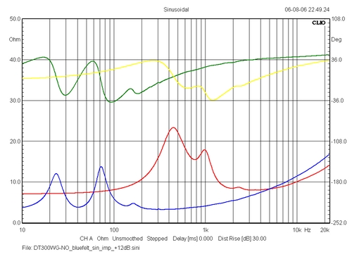
Measurements
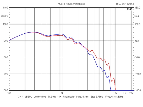
The red graph is the
response of the two C17 drivers from only a 1 mH
series inductor. The blue is when we add the
impedance correcting RC circuit. Where the red
graph very much seems to resemble a true 1st
order roll-off, the blue seems to have a roll-off
of 6 dB/octave from 1-2 kHz. From 2-4 kHz the
roll-off appears to be more like 9 dB/octave and
from 4-8 kHz we have a 12-18 dB roll-off.
|
Impedance of drivers
without crossover attached. The red is the
tweeter with all modifications as described
later.
There's an annoying notch at 160 Hz. Some cabinet
resonance from my test cabs. The final cabs will
be added further bracing. Read first article, C17.
|
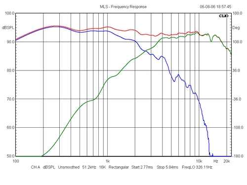
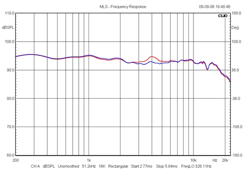
Above the response from
drivers and summed response of the finished
crossover with 2R2 to the tweeter. Close to what
the LspCAD simulation predicted. Maybe even a
little better. Overall we have a rather flat
response and eventually I raised the tweeter
series resistor from 1R5 to 2R2 to reduce treble
response. With 1R5 the sound became a little too
forward.
|
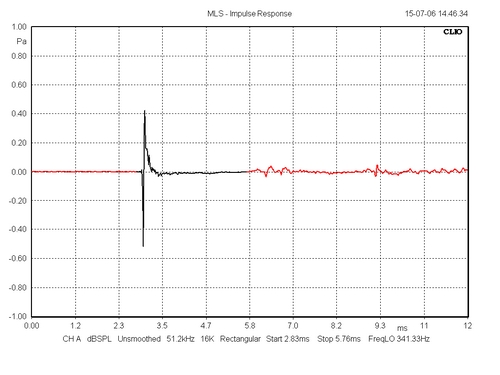
This impulse response is
rather unusual as the impulse from the tweeter
and two midbass drivers appear to start
simultaneously due to the tweeter's voice coil
being some 50 mm behind front panel level.
|
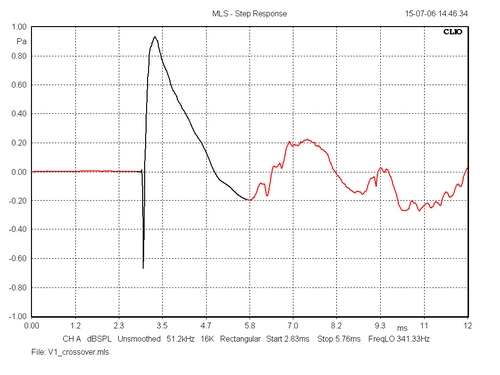
The step response
displays the tweeter connected with inverted
polarity (first sharp peak) and midbass drivers
with positive polarity. This seems to be a
time-coherent system. Due to the wave-guide, the
tweeter voice coil is almost in the same plane as
the C17 voice coils, but due to the first order
filters producing a 90° phase shift, the overall
phase shift between tweeter and bas will be
180°, thus the inverted polarity of the tweeter.
We might try inserting an all-pass filter before
the tweeter to get all drivers connected with
same polarity, but I haven't tried this.
|
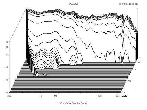
Cumulative spectral decay
from final crossover. Actually this tweeter seems
to have a very clean response with no apparent
resonances except for a small dip at 15 kHz. It
doesn't disturb my peace and it's tricky business
to work around 15 kHz but I'll see if I can
further improve the tweeter mods to smooth the
response for the sake of good order.
|
Impedance plot of system.
A significant rise in impedance around the point
of crossover. However, nothing serious to my
Copland valve power amp. Should you worry about
this from using low-wattage SET amps, read below:
|
Impact on impedance from
adding a LCR circuit across terminals: 0.27 mH +
6R8 + 22 uF. A very easy load to any amplifier
that can run a 4 ohms speaker.
|
Impact on FR from tweeter
LCR (15R + 1.5 uF + 1.0 mH). The minor bump at 4
kHz is removed. And it's audible.
|
The sound?
Well, this DT300-waveguide
certainly changes the sound of the C17 set-up. A
waveguide in front of a dome tweeter sounds different
compared to standard tweeter and transients appear faster
than ever. It's difficult to compare to the first
C17+27TFFC set-up because a lot of things has changed.
Where the C17/27TFFC had a 2nd/3rd order filter we're
here dealing with a 1st order filter. I tried a similar
2nd/3rd order approach to this set-up but the sound
didn't seem to "come out of the box". I all
sounded very nice, really nice, smooth and clean, but it
didn't come to life the way this first order filter does.
First order filters also have their drawbacks due to the
huge overlap between drivers and the mutual colouration
they may introduce, but again, I think the reduced
distortion of the tweeter due to the waveguide plays an
important role here. A good sign is that I generally play
louder with the C17+DT300 compared to the C17+27TFFC. In
the beginning I thought the DT300 had some distortion at
high levels until I realised how loud I was playing. And
the DT300 needed time to break in. The current set-up
does have limitations in terms of overall loudness, but
they can play loud enough. No doubt about it!
It's rare I sit in front
of a pair of new speakers, pulling out old CDs and vinyls
to hear what I missed before. But this time I did. I've
never heard such depth from live recordings as here.
Driver integration is better and one explanation may be
that the waveguide will enlarge the soundwave coming from
the small dome to a size almost equal to the size of the
C17 driver.
Did I hear someone say: "Yeah, right! The guy's got
a new speaker and hear things he never heard
before." I very much quote myself, because we'll
always hear things we never noticed before when we
connect another pair of speakers - because no two
speakers are alike. Nevertheless, this speaker will be on
the agenda for some time before the final cabs are made
and they will be in my permanent collection of speakers -
as representatives of particular interesting d'Appolitos.
They can do things none of my other speakers can do.
The bass from these C17 drivers
is excellent and despite the poor measured performance in
terms of bass extension, the bass appear deep and
powerful. It's very dry and anything but one-note or
mushy. Mind you, the radiating area of the two C17
drivers is around 280 cm^2, close to a 10" driver,
thus we have the bass and mids coming from a huge area
compared to most other small speakers. And I still
consider the C17 a relatively small speaker with an
internal volume of approx. 40 litres.
The C17/DT300 is very much
a "window to the music" rather than a speaker
that "creates music in a room" like the PMS
with its wide dispersion and ease of placement. The
C17/DT300 takes more care in placement and toeing in and
it may be more picky on what drives them. The best I've
heard was from a MingDa 300B push-pull integrated, 20
wpc.
Did I say I never enjoyed the audience's handclapping so
much as from these speakers? My vinyl live recordings are
on the turntable all the time.
Tweeter mods:
 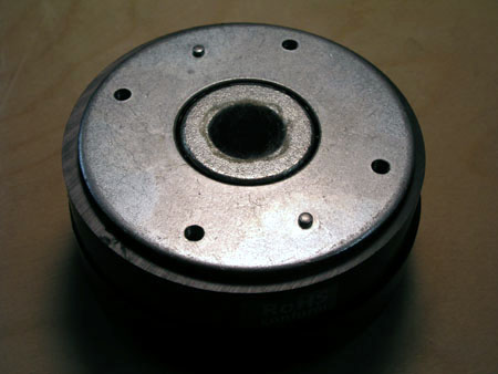
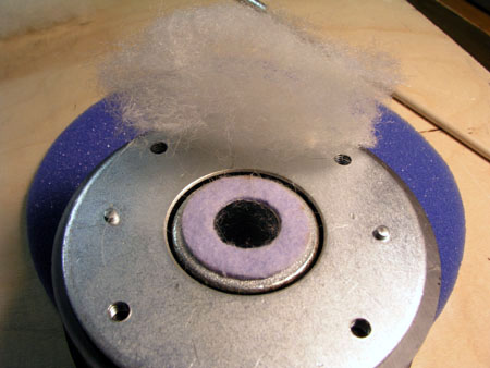
| Remove
the faceplate and the voice coil as seen to the
left. The vented pole piece is covered with some
heavy felt material and the hole through the
polepiece is not damped at all. A bit strange.
Seems like a rather simplistic approach. Why have
a vented pole piece and a damped rear chamber -
and then block the vent? One reason may be that
the felt pad works as an acoustic vent to the
rear chamber. |
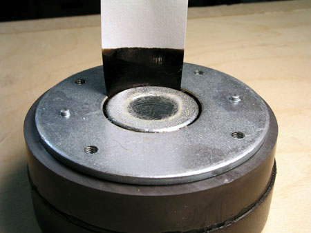 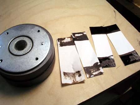
Remove the magnetic oil
with some small sheets of paper - and there's a
lot of oil. Pic to the right.
|
The voice coil needs
thorough cleaning. Use soft paper (Kleenex) to
remove residual magnetic oil. Make sure to remove
all the oil as it adds weight to the voice coil.
|
 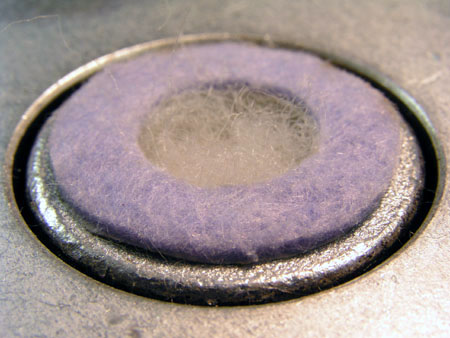
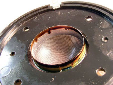
A ring of felt material
(1 mm thich) is glued to the polepiece and 200
milligrams of Monacor MDM3 (2/3 wool + 1/3
polyester foam) is stuffed in the pole piece
vent.
If you think this is too much, you
may get away with only removing the magnetic oil.
And this must be done to make the
crossover work as intended.
After modifying the tweeter I had
both tweeter running fullrange on the MLS signal
for some time to speed up burn-in. I suggest you
let them play full-range music for some time.
These tweeters are quite rugged, so don't be
afraid to ad moderate power.
|
Go to main page
Go to Vifa C17-I
|