DIY Loudspeakers: HOME INDEX UPDATES RESPONSE WHAT'S NEW
PRELUDE
DISCONTINUED Why? The Box Crossover Measurements Crossover Layout Box Pics PRELUDE TWEAKS
|
||
|
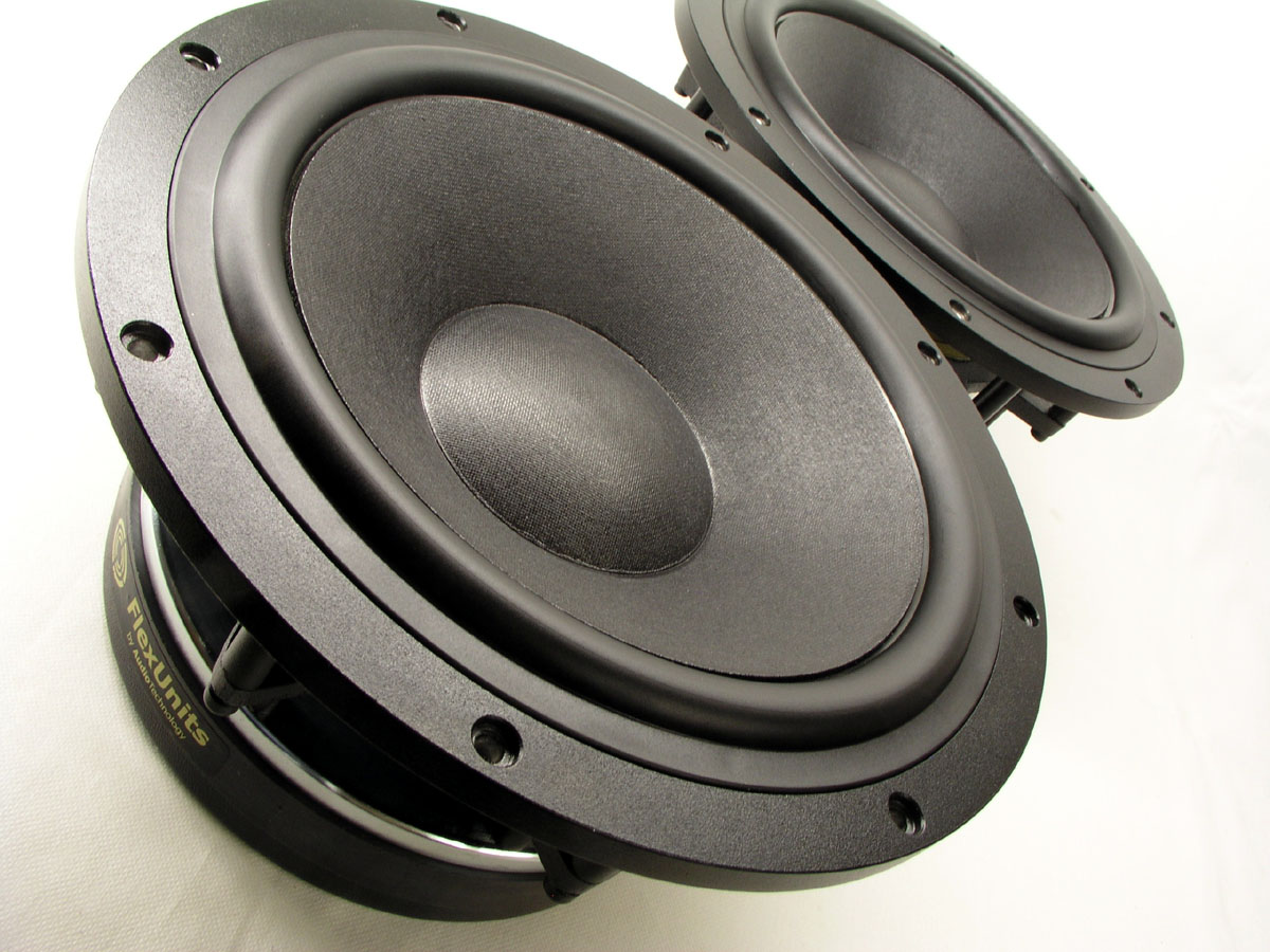
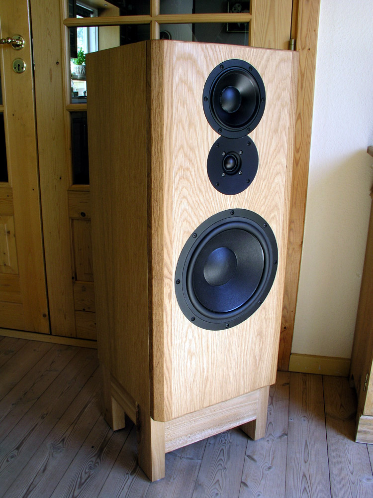
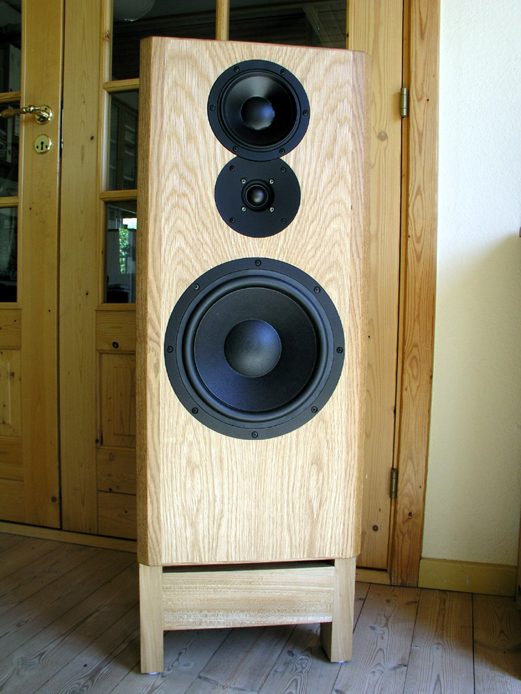
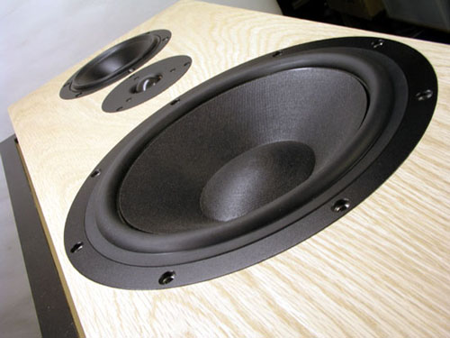
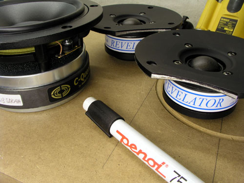
Bass:
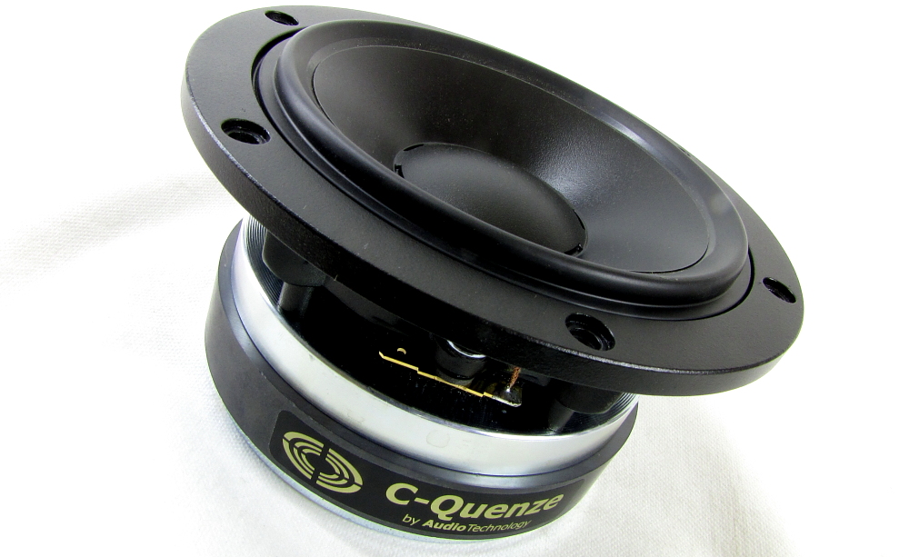
Audio Technology 10C77-25-10 KAP. Mid: Audio
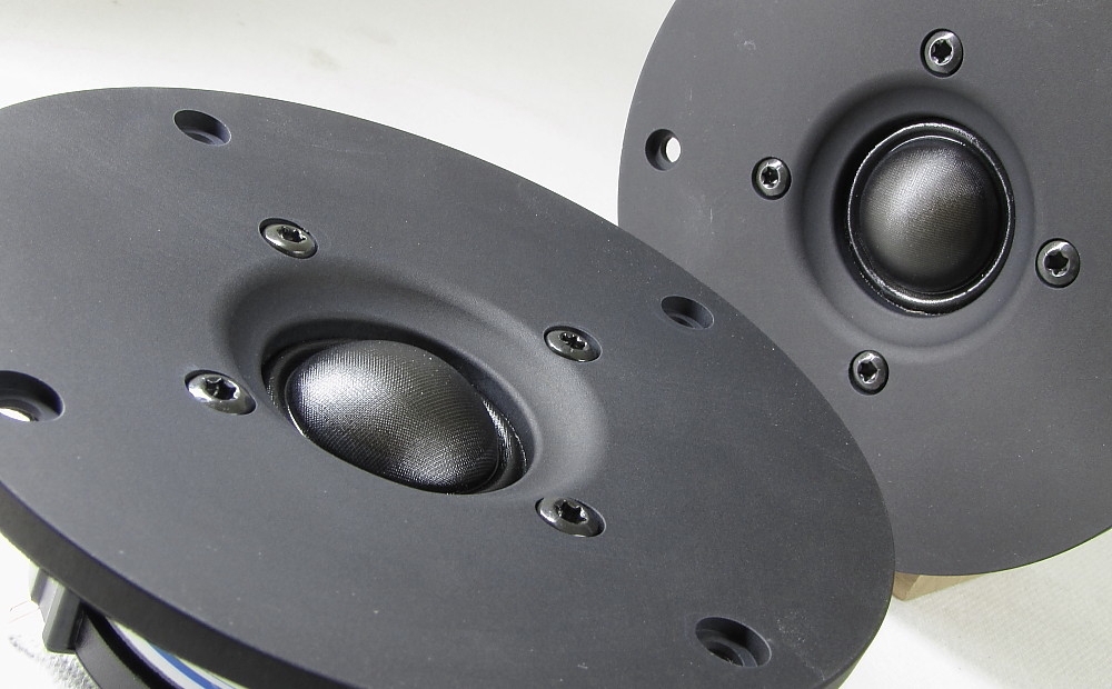
Technology 15H52-06-13-SDKAM. Tweeter: ScanSpeak
D2905/9900.
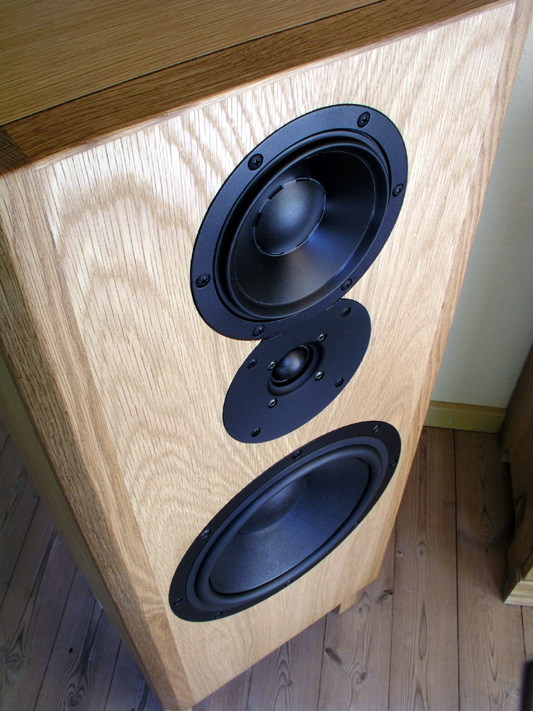
The middriver comes with new rubber surround, optimised for better air-flow and termination of cone energy, underhung voice coil, 6 mm windings in a 13 mm gap. Download driver specs: 10C77 - 15H52 - SS 9900 The actual 15H52 varies from the one shown on the PD in having an underhung voice coil. The correct type used here is 15H52-06-13-SDKAM, Re = 5.5 ohms. (SDKAM: SD = symmetric drive. KA = basic kapton voice coil former reinforced with aluminium. M = middriver (special rubber surround)) This may be an odd place to start, but why another speaker? The world is full of speakers and don't we have enough? From mails coming in, the appetite for new speakers in the diy community is endless. Curiosity and the passion for making something better than last time is the main driver. This must have been going on ever since we sat around the fire carving bows and arrows. How do I make this arrow fly faster, with more precision, with better penetration? If only.... then I would only have to go hunting half day and the afternoon could be spent sitting in the shadow of the trees playing my bone flute - until I get bored and start thinking: "What if..?" Anyway, this isn't about arrows or bone flutes, rather sophisticated loudspeaker drivers that may enable us to get a little closer to the music, reveal more detail and provide an overall more truthful sonic image of what was going on behind the microphones capturing an acoustic event. The construction shown here will offer you an opportunity to reach into serious high-end, that is: If you make rock solid cabinets, if you damp them well, if you offer serious money on drivers and crossover components - and if you have a good amps and source material, the latter not least important. All of this doesn't come cheap and we're into the area of diminishing return from our investment. What we should get from expensive drivers is the ability to play louder with less distortion compared to el-cheapo drivers and here you get it. Some people question the value of expensive crossover components like super caps, etc. My response to this is that if you can't hear the difference between a standard cap and a super cap, your amps, your CD player or turntable cartridge simply isn't good enough. During construction and crossover optimisation, the Morel CAT-308 was the tweeter in place and did a damned good job. However, modelling a large number of tweeters, it was found that the venerable ScanSpeak D2905/9900 not only allowed better phase integration, simpler crossover, better sound, thus the 9900 it's going to be. The slightly concave face plate adds distance to the dome and impulse response could be further improved. The low Fs allowed a simple 2nd order LR to be established with as few components as possible. I like that! Ideally the CAT-308 would require a single cap and two notch filters to shape the 2nd LR roll-off although a single LCR circuit did well for the listening test. With SS 9900 in place a perfect 2nd order LR roll-off could be had from a RL circuit to ground. The 9900's impedance peak at 500 Hz needs flattening from a LCR circuit. Serious listening test were performed w/wo this notch filter and it was impossible to hear any difference, but for the benefit of the doubt it stayed in place. View schematics below and read comments on crossover development. The PRELUDE will offer you a rock solid bass playing high or low, a fully integrated midrange and treble with some of the best treble I've had due to driver quality and the low-order filters employed. The PRELUDE will handle anything from classical guitar, vocals and trio-jazz to heavy metal. Give it some of the best 100 watts you can afford and you may even throw a Saturday evening party.
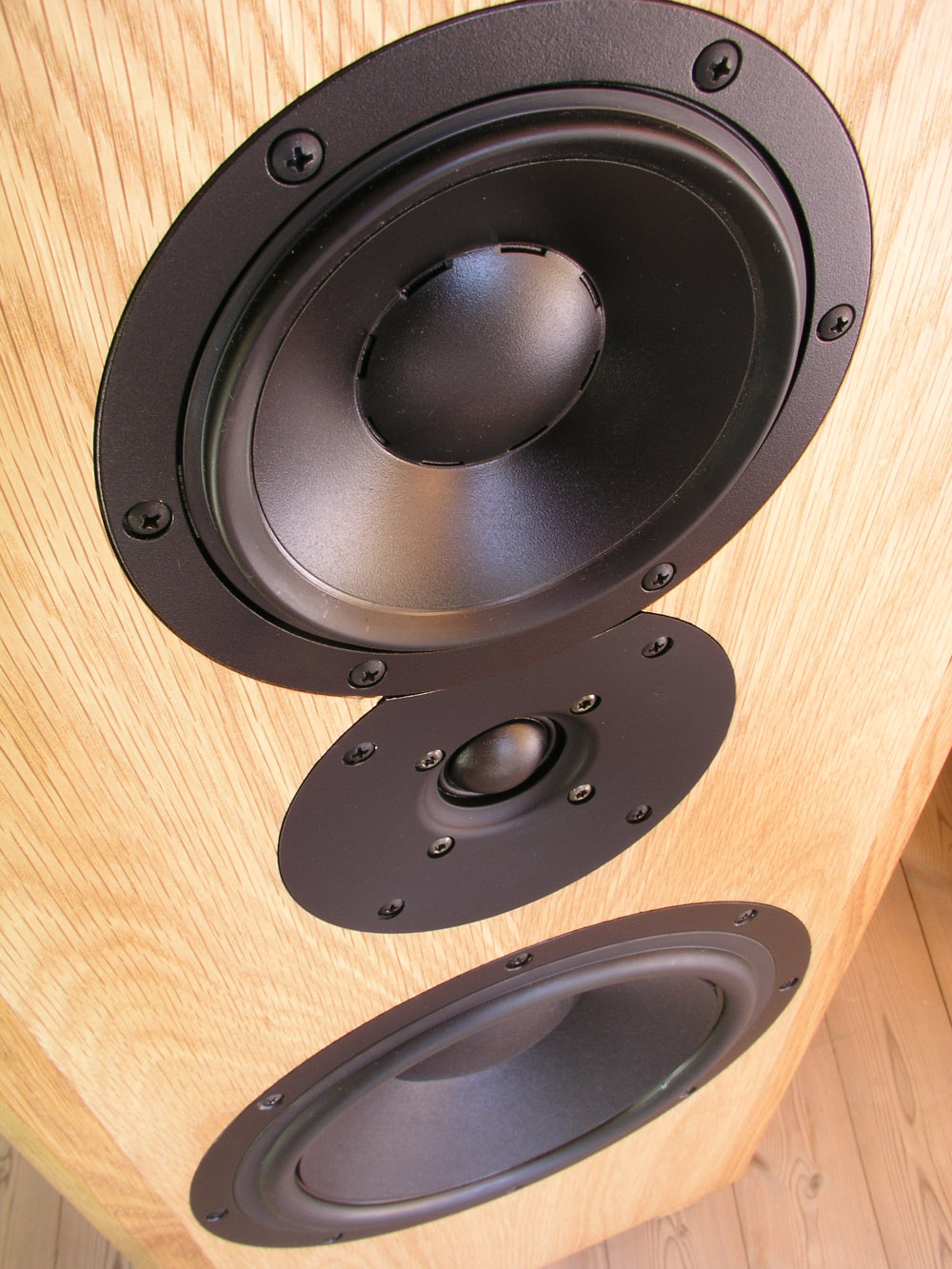
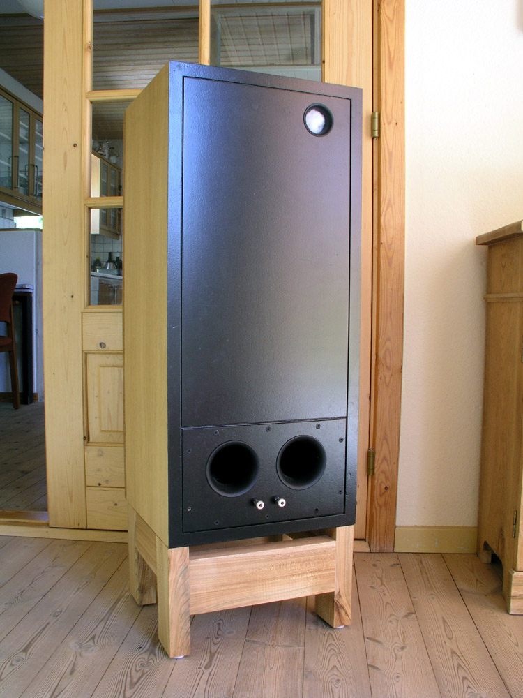
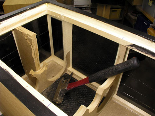
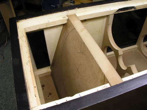
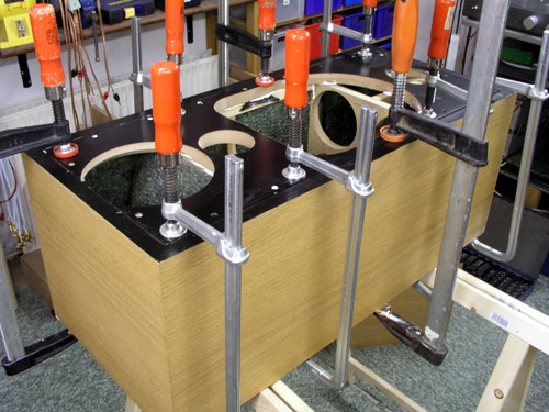
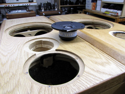
The aim of this cabinet construction is to make a rock solid enclosure for the AT drivers, so be generous with bracing. Next I wanted the midrange at ear height, thus a small stool to lift the speaker to an overall height of 1 meter. The stool is 16 cm high and some spikes or whatever adds to the final 20 cm base height. Finally I wanted a cabinet where most diy'ers can follow in terms of overall complexity. No curved panels or fancy forms that only CNC machines - or talented diy'ers - can cope with. No, this is not a skinny runt of 18 cm width, rather a 36 cm (14") wide baffle providing acoustic support for the drivers and enabling simplicity of crossover. Regarding box size and tuning: Please read here: http://www.troelsgravesen.dk/10C77.htm Final box shown here is around 55 liters net volume (for bass driver alone) depending on use of bitumen pads, amount of bracing, volume taken by crossover, etc. I recommend a port tuning of 30-33 Hz. Use 2 x vents @ 68 mm diameter and 220 mm length. Download excel file to calc. vent length here. Note excel file is set for one port. When you use two ports, double vent length.
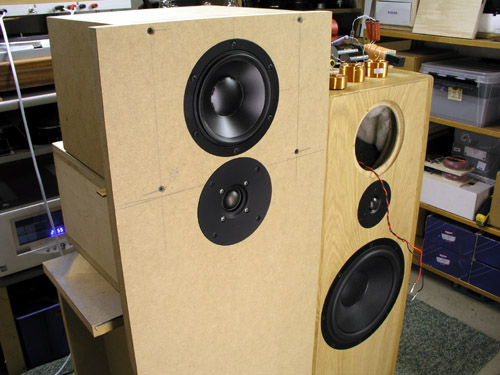
Work on this crossover has been ongoing for 4-5 months, much longer than any other speaker I've made and eventually produced "Siri's Killer Note". The reason for this is not that the drivers are particularly difficult, and going the standard route of 2nd/3rd order filters, the crossover was in place in a few hours. But these drivers are not any drivers and upper mid and treble presentation suggested more work to be done, thus a whole range of crossovers were simulated and tested for the mid-tweeter section going from 3rd LR to 2nd LR to 1st order filters and eventually a combination of LR2 and 1st order Butterworth did what I was after. In reality true 1st order filters for all drivers cannot be realised and the acoustic roll-off is indeed often something between a true 1st order Butterworth and 2nd order LR and depends on how far above or below point of crossover we want the slope to follow target response. What often happens during crossover development is that you reach a certain point where the sound is very good, but measurements suggest more to be done and slowly you improve measured performance - and decrease sonics. Reaching crossover version 7 mkII, everything looked great - but magic had gone. Now bass and mid integration was pretty much in place but what happens here will also have an impact on upper registers and in reality I had reached a rather perfect LR2 topology for both mid and tweeter. The close-to-first-order mid-tweeter filter of previous versions was gone - and so was the magic. Hmm... Back to LspCAD and some more late night hours' simulation and crossover soldering. When the final middrivers were at hand, another round of crossover fine-tuning had too be done, but nothing serious compared to the temporary 15H52-15-06 SD I had used for initial experiments. LR2 between bass and mid
was run for a long time, but having the mid on
top, driver integration wasn't perfect, thus the
1st order high-pass to the mid was tried and an
LCR circuit takes care of the mid's impedance
bump at 80 Hz. The mid cabinet has a 40 mm vent
and Fb = 47 Hz, but eventually the vent was
stuffed lightly with damping material and the
impedance flattening circuit introduced. This
works. Actually the LCR circuit also works very
well with the vent not stuffed, so take your
pick. The sound is slightly different and I
strongly recommend adding the vent for
experimentation with closed, aperiodic and vented
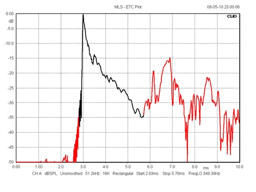
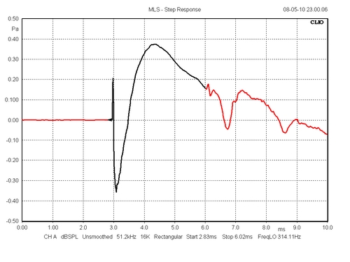
mid cab. The final crossover is asymmetric, providing LR2 slopes to bass and tweeter and 1st order to the middriver. Thus proper phase integration is achieved with enhanced impulse response. In a commercial add this would account for perfect transient response, time-aligned, zero time and phase distortion and bla bla bla.... But let's be honest and agree only e.g. QUAD ESL speakers come close to these virtues. Dynamic drivers can do a lot of things electrostatics can't, and as always there is room for improvements. Looking at the step response below, we're close to a perfect time alignment between mid and tweeter and this truly pays off in terms of transient response and enhanced overall transparency. Adding an all-pass section to the tweeter to render same polarity for mid and tweeter was tried and didn't pay off. Serious listening tests were performed but I'm really not sure that same polarity pays off as long as proper phase integration is accomplished. It may be a give-and-take situation where the added series components detract from any possible benefits of same driver polarity. The crossover seen below may seem a bit complex to some people and here are my comments, click here. I've already had the question on the differences between the middrivers tested and I had three identical pairs except for voice coil former material, alu, kapton and kapton/alu. The voice coil former material has a significant impact on performance, particularly on upper mid and treble range and what works the best may depend on choice of tweeter and crossover topology. The impact on sound is very subtle and the choice was hard. The mids with alu formers had the best (smoothest) frequency response but eventually the kapton/alu was chosen based on sonics and please do not ask how they differ, because if I put in onto paper it would be black and white - and it isn't. The choice of voice coil former material will depend on the actual application, and we can't simply conclude one material is better than the other. Read here at Audio Technology website about voice coil former materials: What is the difference between Kapton and aluminum, question 3.
All kit componentsmust bought locally. AudioTechnology drivers must be bought
from manufacturer: All technical questions to me at troels.gravesen@hotmail.com Crossover Layout
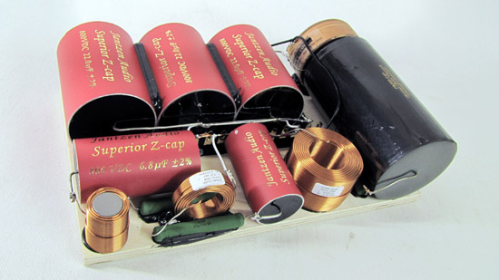
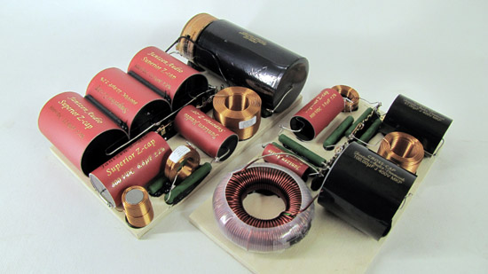
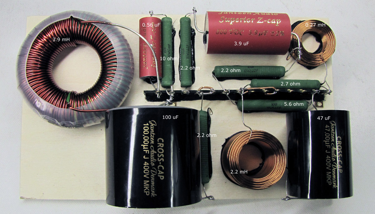
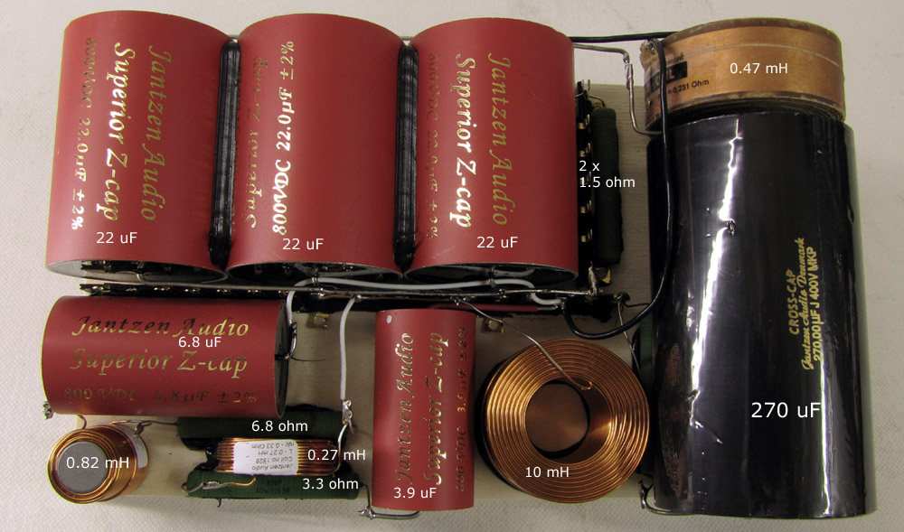
Getting the final crossover in place is always an exiting moment. The crossover prototype is always a mix of bundled caps, electrolytics in a few places, long wires, etc., and although working perfect technically, there's usually a minor change in overall sound - and usually for the better when the final crossovers are in place. The PRELUDE didn't deviate from this practice. Treble and mid appeared smoother and tighter, but the biggest surprise came from the woofer. This 3.9 mH C-Coil with an all time low DCR of 0.08 ohms, just had a significant impact on bass performance being tighter and more precise. Not the last time I'll be using these C-Coils. Fortunately the final crossover didn't suggest further work on balancing mid and tweeter level.
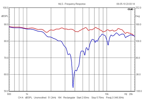
resp
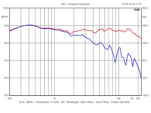
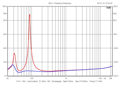
Left: Impact of mid
high-pass section LCR circuit (10 mH + 270 uF +
6R8). The reason for showing this is that in a
commercial speaker this circuit would definitely
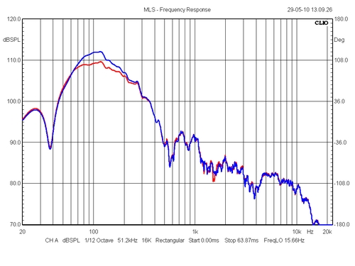
be I think this is enough. Basically measurements tell very little - if anything - about how a speaker actually sounds.
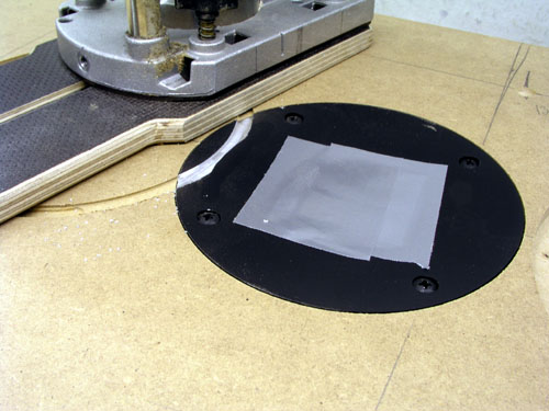
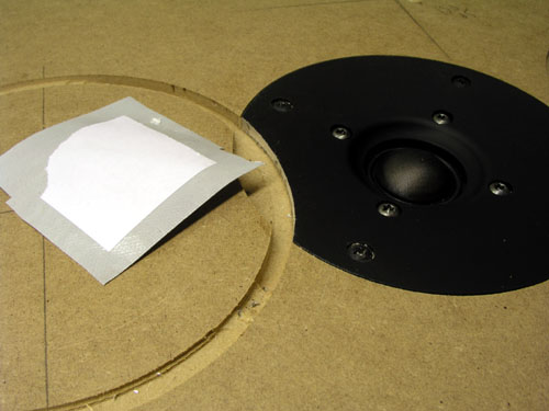
9900 routing
Box damping.
Marlen/Russia
suggested an interesting option (read
S.D.Batti,
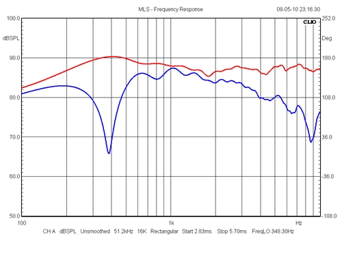
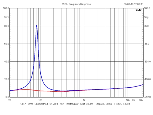
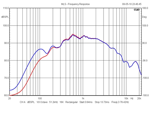
Upper:
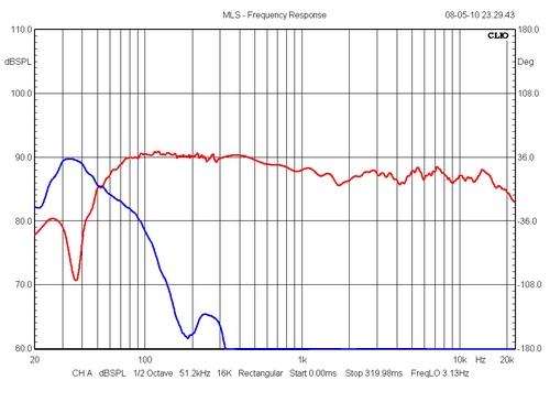
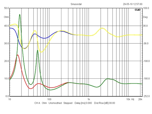
As can be seen we have some 2-3 dB difference at
100 Hz and the notch filter produces and overall
smoother response. All in all this makes
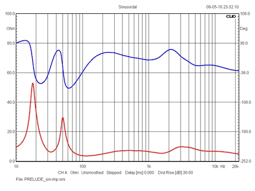
better impedance in the 100-200
Hz area but ~2 ohms lower around 30 Hz. The huge
phase shift at 50 Hz is gone, but still remains
around 25-30 Hz. Jantzen Audio does have a 18 mH
coil, DCR = 5.7 ohm (coil # 1699), which seems
perfect for the application. Only thing is that
we may have to use a 330 uF electrolytic
capacitor. The CrossCap range does include a 330
uF value, but it is huge: 68 x 110 mm and I
hardly have room for more. And it's around 70 USD
each.
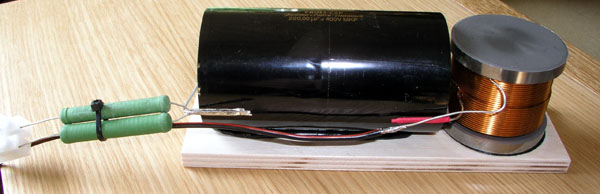
The final LCR circuit,
here temporarily set-up for test. The board will
be placed on rear panel behind bass driver. The sonic impact from adding the bass LCR circuit is a more balanced and subjectively pricise bass. Strangely enough, bass extension appear enhanced too. Conclusion: The LCR circuit has come to stay, but use a standard 330 uF electrolytic capacitor here. No need for a humongous PP at this place. Last but not least: Tweeter attenuation
This is one thing you
must do. Tune tweeter level to suit your taste,
your room and not least speaker position.
My final value for R2021 has changed from 3.3 ohm
to 4.7 ohm. I guess most will settle on 3R3, possibly
3R9. 4R7 may be too laid back for some people, but to ears makes
the best balance of basic notes and uppertones.
|