Ellipticor-TQWT
Copyright 2022 © Troels Gravesen
Go to on this page:
DRIVERS CROSSOVER CABINET WORKSHOP PICS MEASUREMENTS SPEAKER-KIT CROSSOVER LAYOUT
December 2022:
More than a year ago a friend brought me his TQWTs fitted with
Ellipticor drivers and a very simple crossover, a sine-cap crossover, as
you may know from my
Ellipticor-3 loudspeakers. We sat them up in my living room and they
sounded really well. He had used 18WE/8542T00 and D3404/552000 drivers.
0.6 mH to the bass and 6R8 and a 0.22 mH coil for the tweeter. And not
only that, the mid-bass and tweeter had same polarity. Since 2017 I have
done quite some work on the Ellipticor drivers and I got suspicious
seeing the crossover and wiring and did some measurements showing quite
a decline in the treble area due to out-phasing and an elevated response
in middle-mid and upper-mid to lower-treble.
Hmm.... Why didn't it sound worse?
There is probably not any clearcut answer to that question. What was the
target here was a 1st order slope with no baffle step compensation, thus
elevated response in upper-mid/lower-treble. This gentle 1st order
filter will introduce very little phase shift. In fact we only have a
difference in minimum phase of about 100o between the two
drivers and in a perfect world the phase shift should be 45o
in opposite direction of both drivers at point of crossover, thus pretty
close to ideal. And in addition to this we can find a point in space
where we have a decent summation producing a - almost - flat response.
We could further improve on this by introducing a baffle step
compensation by adding a 1 mH coil by-passed by 4R7 to get a linear
response up to 4 kHz. The main inductor (L2) also increased to 0.82 mH.
Still, this wouldn't change minimum phase from the original crossover,
but tweeter attenuation would have to be increased considerably (~15
Ohms) and dZ set to zero, which means the two drivers must be perfectly
time-aligned to produce a decent flat response.
This raises the question if what we measure is really equivalent to what
we hear. The microphone picks up the response in a very specific area,
much less than 1 cm^2. What hit our ears are from a much larger area,
first of all having two ears at different locations, and not least that
what we hear is the sum of direct sound and all reflections from the
room. We hear sound coming from the floor, the ceiling and the walls
surrounding the speaker, thus we may not be able to actually hear that
in specific locations we may have a deep suck-out from the driver's
response out-cancelling each other.
In addition to this, 1st order filters are generally gently on the ear
due to very low phase shift, that is - if the drivers behave well and
doesn't have any serious break-up nodes - and these Ellipticor drivers
have these properties.
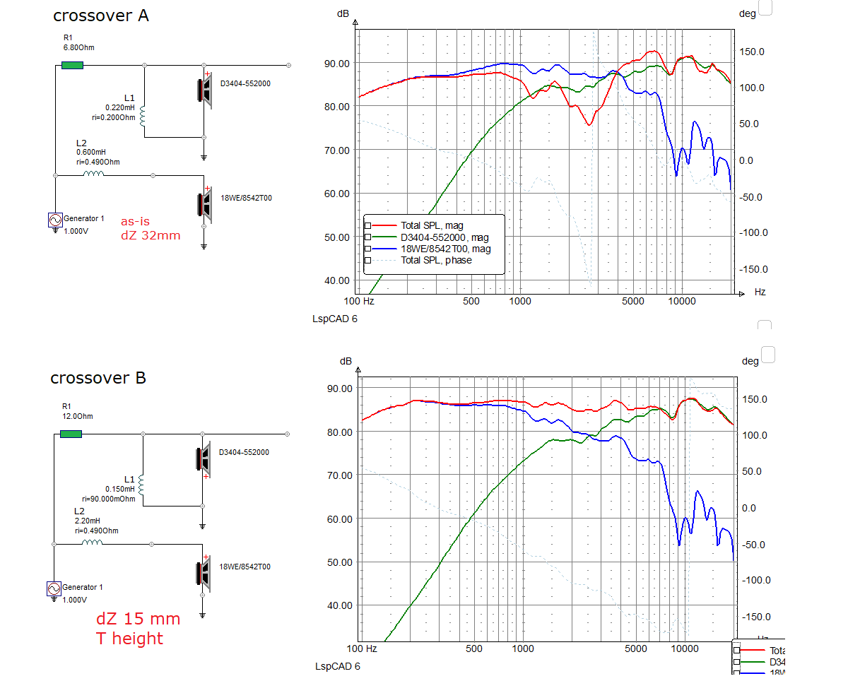
My personal take on this TQWT is some time-alignment from adding a 21 mm
stepped baffle making dZ of around 15 mm at a point between the two
drivers - and a new crossover (B), where the bass series coil both
handles the baffle step loss and the low-pass filter. Next a 1st order
filter to the tweeter that brings it down in level to match the mid-bass
- and not least inverted polarity to the tweeter providing perfect phase
integration and summation.
I sometimes have a mail asking for the baffle step loss compensation and
the thing is that I (almost) never worry about baffle step loss as it is
- so to speak - built into the bass low-pass filter. You measure the
response from the bass and starts modeling the low-pass filter until you
have a flat response. This almost never fails.
Some people claim drivers must have same polarity to sound
right - and I wish all happy in their beliefs. From a properly executed
crossover, I have never found this to be critical.
Almost all my construction have a measurements section and they are all
introduced with some warning to what may be extracted from these graphs.
We think measurements may give us an idea about the sound of a speaker
- and the truth is that they don't. Final system sensitivity and final
system impedance may be of interest for the choice of amplifier, but how
the speaker really sounds only our ears can tell.
Should you be among the lucky few to have these drivers on the shelf, I
hope this may inspire you to have some fun Christmas holidays in the
workshop.


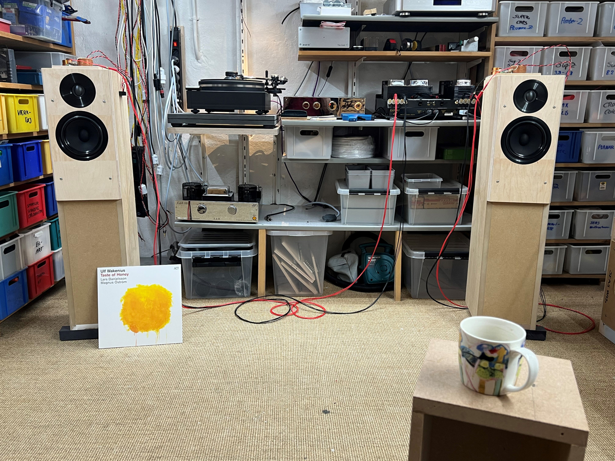
Crossover A:
Ulf Wakenius is a strong favourite of mine and this tribute to Paul
McCartney is a fine melodic exercise in the back-catalogue of Sir Paul.
This comes out really well on the v1 crossover, a vivid and strong
midrange, sometimes too strong and the upper mid can become shrill,
which was expected from bright tuning as seen from Fig. 1.
Sinne Eg: Strong vocal that sometimes comes come out well, but other
times become too shrill - excessive upper-mid/lower-treble. But all in
all better than anticipated.
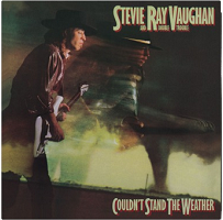
Stevie: Well, great bass from this modest cabinet and relatively small
18WE driver. Overall better sounding than anticipated, but still too
bright compared to other more flat tuned speakers.
Given the tweeter is having it rough here, only protected by 6R8 and a
0.22 mH coil, it does really well and even on the Stevie record with its
deep bass it doesn't suffer any dramatic excursion.
Lori Lieberman: Bought from recommendation by Michael Fremer.
Impressive recording of instruments, not so much of her voice... I
checked the recoding with different speakers and different cartridges -
same result. The cover notes says Neumann M49 microphone for vocal.
Strange! Her voice has some weird phasey quality that is really hard to
describe.
And the
vinyl is disappointing, sounds like noisy recycled vinyl. Summary: Not
recommended.
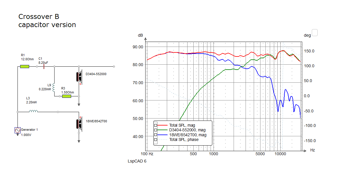
Crossover B, flat baffle:
To overcome the baffle step loss and at the same time adding the
low-pass filter to the 18WE driver, L2 was increased to no less than 2.2
mH. This does it. At the same time L1 was reduced to 0.15 mH and R1
increased to 12 Ohms. With such an increase in the value of L2, then we
have to reverse polarity of tweeter for proper summation.
All three records above fall into place and we now have a better balance
of basic notes and overtones.
Crossover B, stepped baffle:
Slightly improved soundstage and optimal listening height somewhere
between midbass and tweeter.
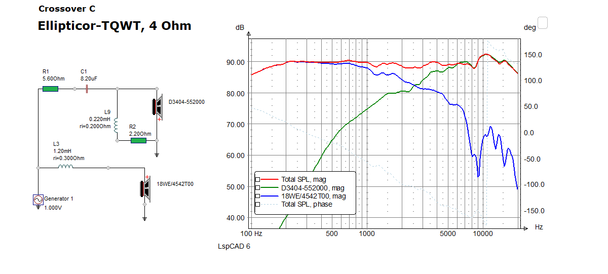
Crossover C:
4 Ohm version with capacitor coupled tweeter. The sound of B, just a bit
more dynamic. My favourite.
Basics:
2-driver speaker.
Dimensions: 23 x 36 x 100 cm, WxDxH.
System sensitivity: 85 dB/2.8V/1 meter.
Impedance: 4-8 Ohms.
Power requirement: 20+ watts/channel.
Power handling: 100 watts.
Useful links (Please
follow all links before e-mailing!):
http://www.troelsgravesen.dk/tips.htm
http://www.troelsgravesen.dk/tips.htm#CONSTRUCTION_OF_CROSSOVERS
http://www.troelsgravesen.dk/crossovers.htm
http://www.troelsgravesen.dk/LCR-RC.htm
http://www.troelsgravesen.dk/Inverted-Polarity.htm
http://www.troelsgravesen.dk/choices.htm
http://www.troelsgravesen.dk/power-handling.htm
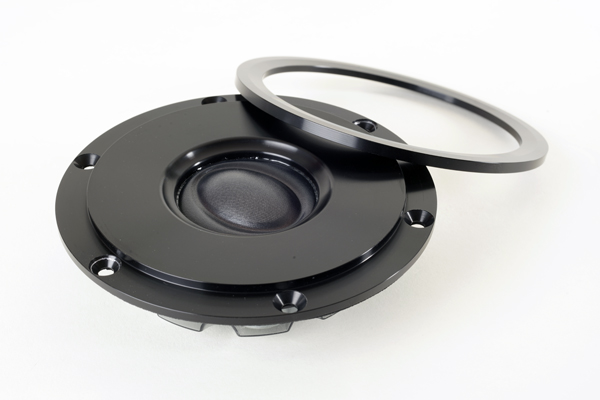
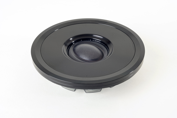
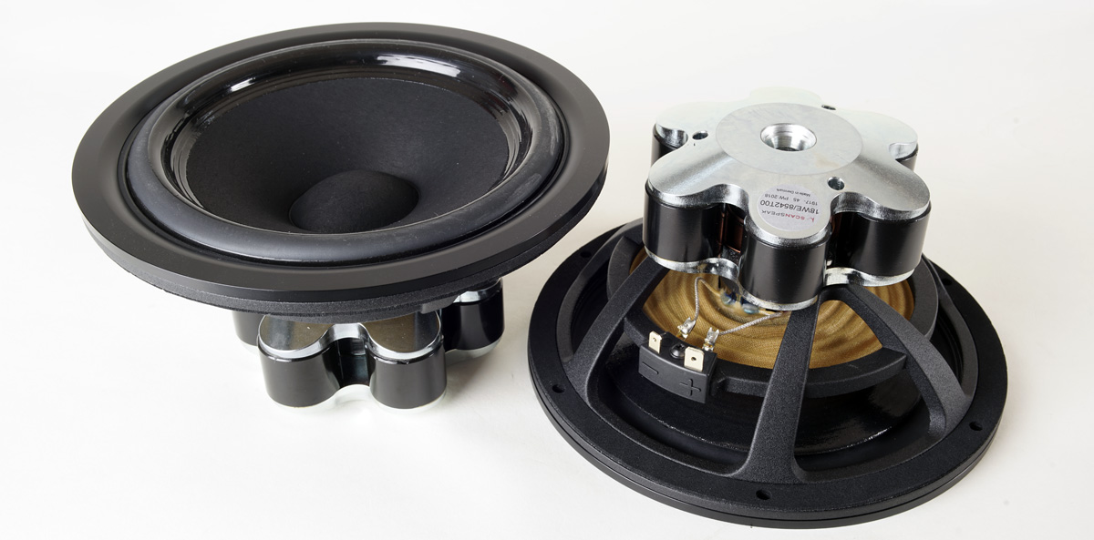
Download specs here: D3404/552000 18WE/8542T00
Stop press:
Having listened a while to the 8 Ohm version, why not also try the 4 Ohm
18WE/4542T00. So, after some fine-tuning this came up - and apparently
my EAR-841 amp liked it a lot. Efficiency of the two speakers are
essentially the same, but the enhanced sensitivity made an impact. This
EAR-861 is wonderfully weird! As always - and this goes for quite some
tube amps to my experience - even ~4 Ohm speakers sounds the best from
its 8 Ohm tabs. There was a strong sense if increased dynamics from this
4 Ohm TQWT.
Impedance stayed above healthy 4 Ohms, so no nasty load at all.
Considering the enhanced dynamics of the 4 Ohm version I have to make a capacitor version of the 8 Ohm version, crossover B and hear what happens. You never get finished with these things...some other time.
In reality the sin-cap topology adds a resistor across the bass driver and changes the impedance significantly:
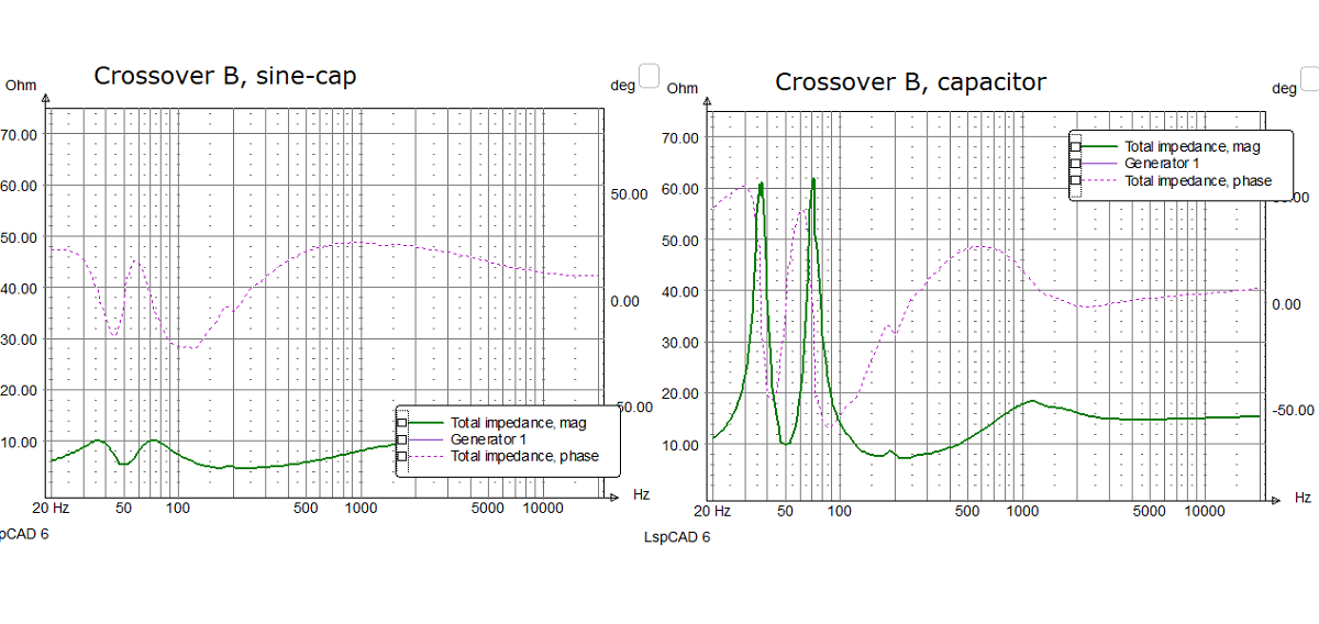

click image to view large

Modified cabinet with stepped front panel.
The front part of the cabinet was damped with 8mm felt materials and a piece of 20 x 50 cm acoustilux. Top panel just had felt damping. Cabinets should be some 25-35 mm from floor level.
First time setup from crossover A.
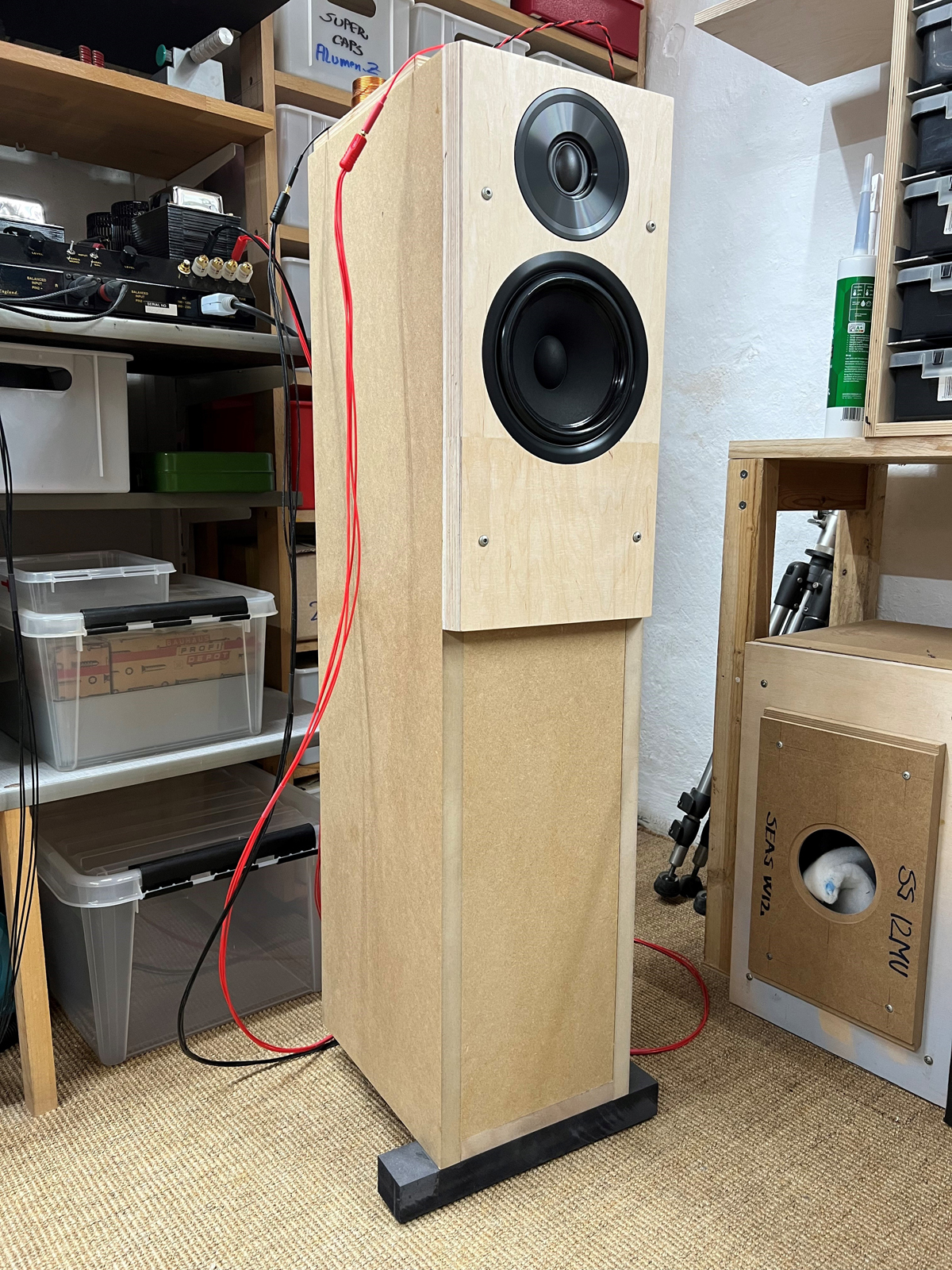
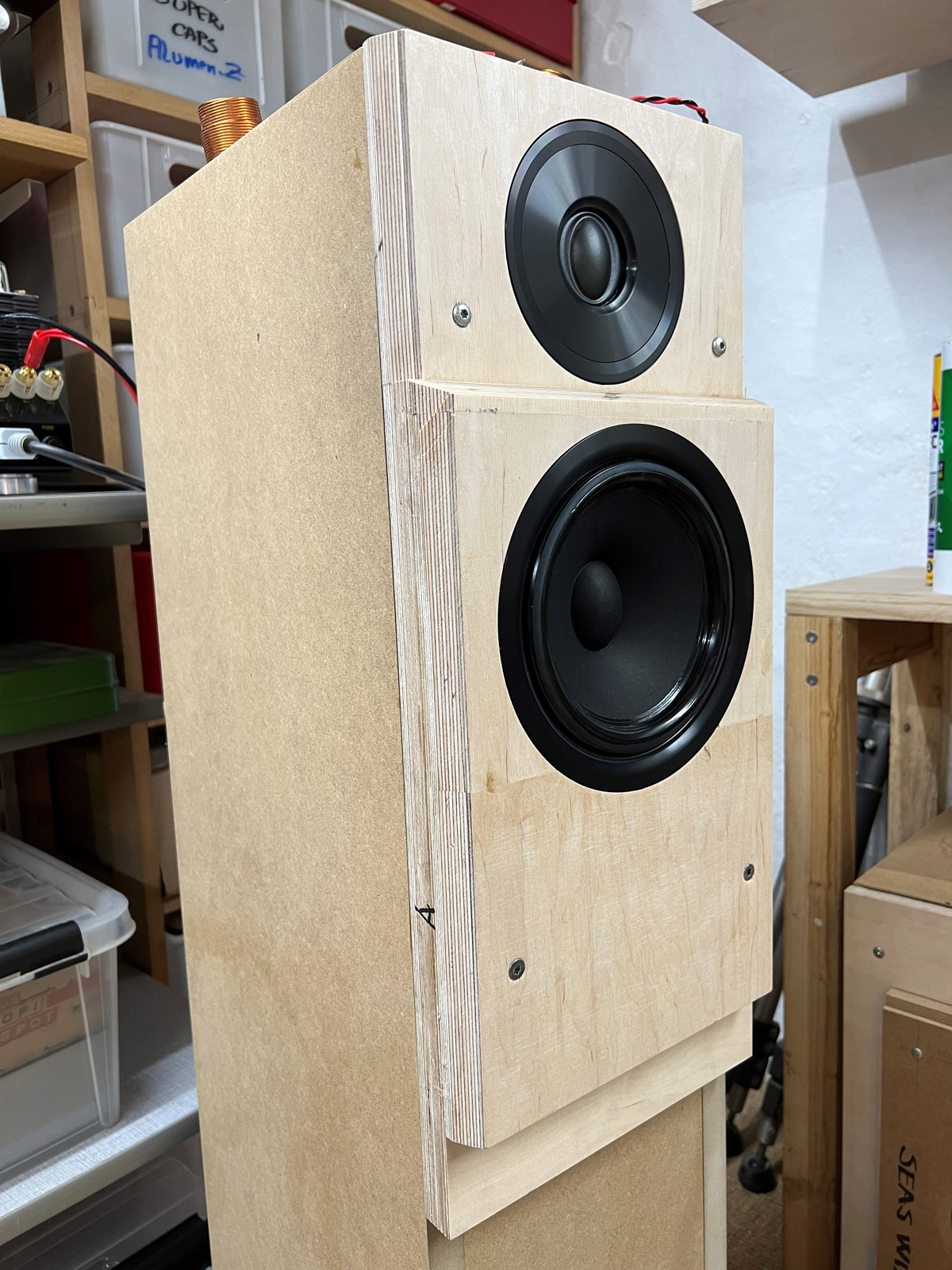
The modified front panel.
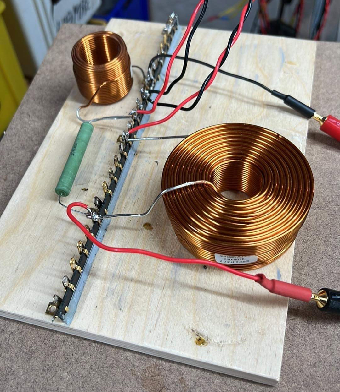
Crossover B.
Crossover C.
A few comments on
MEASUREMENTS before you start interpreting the readings below.
First of all, if we think measurements will
tell us how a speaker sounds, we're wrong. The perception of sound is
way too subjective to be reflected in any measurements we can perform. A
loudspeaker system is meant to give us a satisfying idea of an acoustic
event and for some people a pair of 5 USD ear-plugs are enough, others
spend 200 kUSD on a truly full-range pair of speakers - and the latter
may not be happier than the former.
Measurements may give us an idea of tonal balance of a system, i.e. too
much or too little energy in certain areas, although dispersion
characteristics play a vital role here. A two-way 7+1 and a three-way
7+4+1 may display similar horizontal dispersion, yet sound very
different. Measurements may tell us about bass extension if far-field
measurements are merged with near-field measurements. In addition to
this, ports may contribute to bass extension. Most of we diy'ers do not
have access to an anechoic room for full-range measurements from
20-20000 Hz.
What cannot be seen is what kind of bass performance we get in a given
room. Bass performance is highly dependent on in-room placement of your
speaker and the same speaker can be boomy in one place and lean in
another. Actual SPL level at 1 meter distance and 2.8V input is useful
for en estimate of system sensitivity and combined with the impedance
profile may give an idea of how powerful an amplifier is needed to drive
the speaker to adequate levels.
What measurements do not tell is the very sound of the speaker unless
displaying serious linear distortion. The level of transparency, the
ability to resolve micro-details, the "speed" of the bass, etc., cannot
be derived from these data. Distortion measurements rarely tell much
unless seriously bad, and most modern drivers display low distortion
within their specified operating range.
Many people put way too much into these graphs and my comments here are
only meant as warning against over-interpretation. There are more to
good sound than what can be extracted from a few graphs. Every graph
needs interpretation in terms of what it means sonically and how it
impacts our choice of mating drivers, cabinet and crossover design.
What measurements certainly do not tell is the sonic signature of the
speaker, because speaker cones made from polypropylene, aluminum,
Kevlar, paper, glass fiber, carbon fiber, magnesium, ceramics or even
diamonds all have their way of adding spices to the stew. Nor do
measurements tell what impact the quality of the crossover components
add to the sound, from state of the art components to the cheapest of
coils and caps, they all measure the same if values are correct, yet
sound very different.
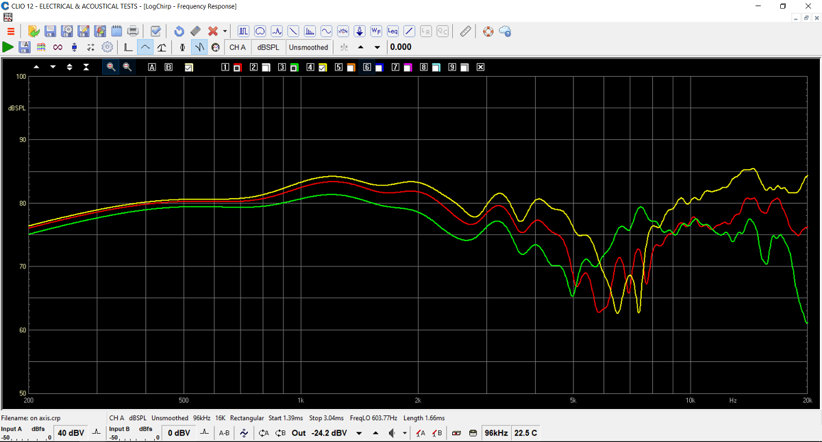
A quick test of my friend's speaker at different locations.
Not my usual measuring conditions, but clearly show quite an elevated
response in the 800-2500 Hz region and outphasing around 5 kHz.
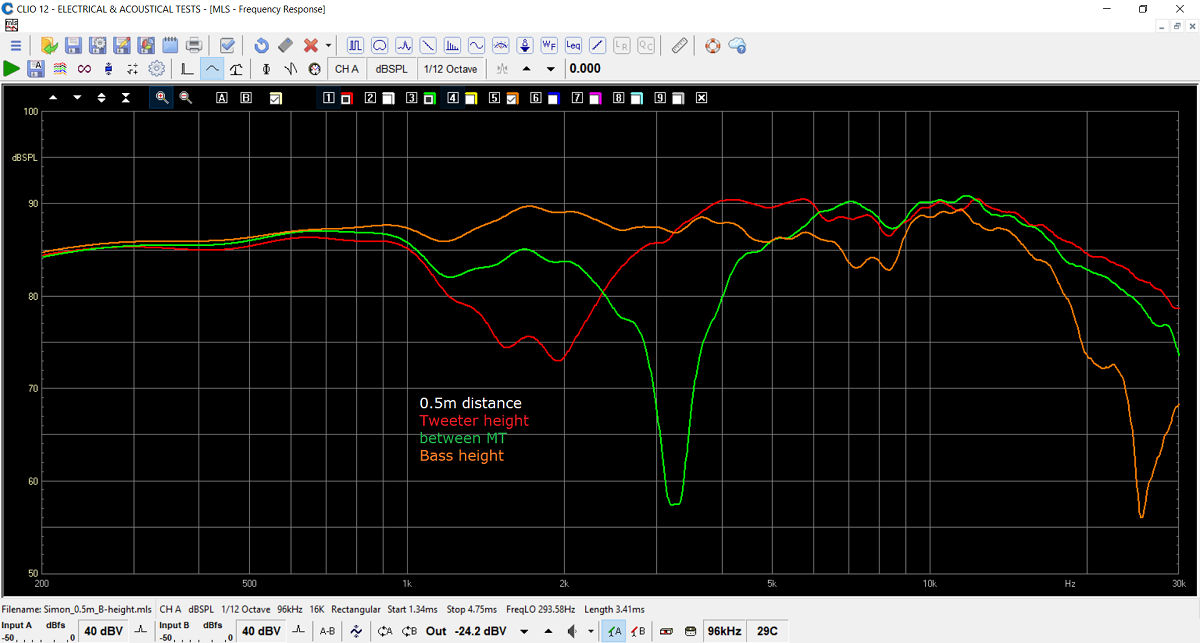
Fig. 1. Response from crossover
A. Response measured at 0.5 distance at various height. Response normalised for 1 meter/2.8V.
System sensitivity around 85 dB (midrange) with a rising response from
1-15 kHz, some 3-5 dB above basic level.
Response from crossover B and flat baffle.
Red at bass height, green at point between bass and tweeter. Orange at
tweeter height.
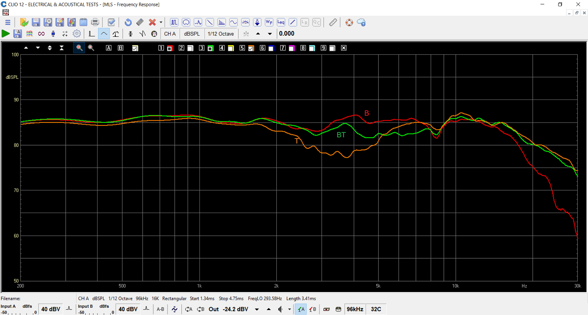
Stepped baffle
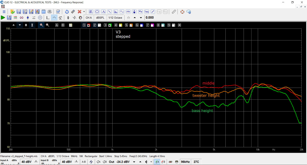
Crossover B on stepped baffle. Measurements @
0.5 meter distance.
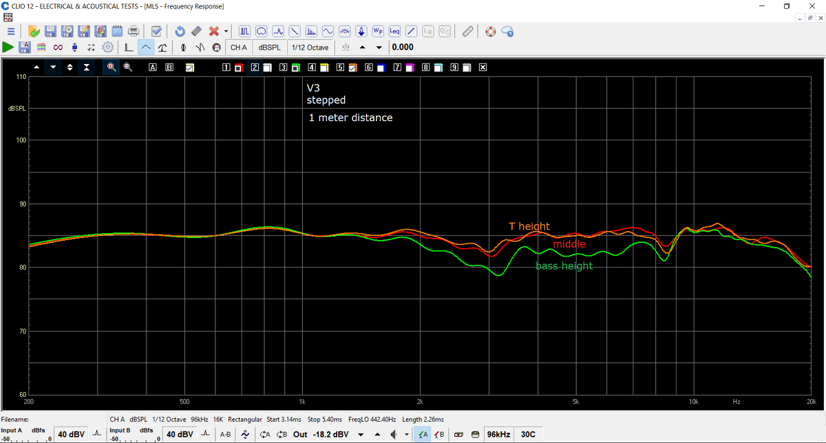
Same measurements only at 1 meter distance.
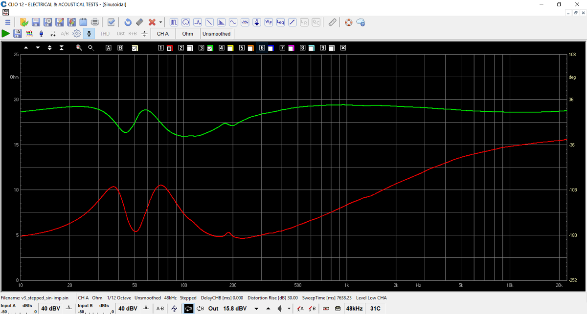
Crossover B, stepped baffle. Final system
impedance, red. Green = electrical phase.
From the fairly short horn we see a tuning frequency of around 50 Hz.
It plays great bass but not bedrock bottom bass - as was expected.
Crossover-C
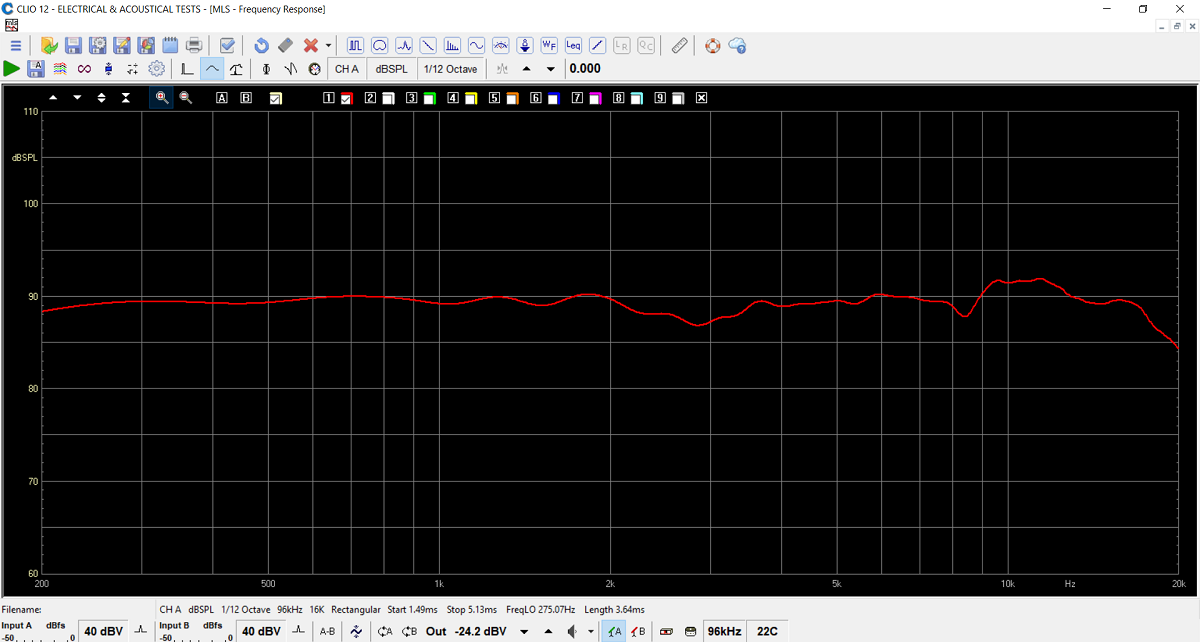
SPL @ 0.5 meter at a height between drivers.
Normalised for 2.8V/1m.
As can be seen system sensitivity has been increased significantly.
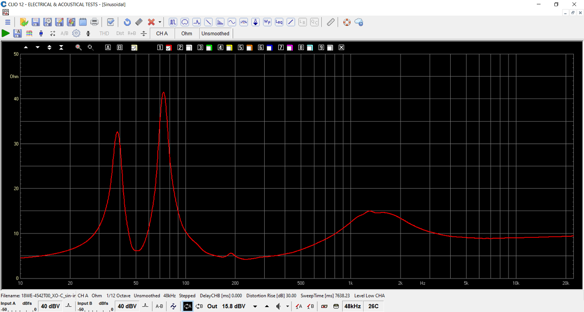
Impedance of 4 Ohm system. As can be seen
getting rid of the sine-cap tweeter circuit increases the peak height of
the bass. Minimum impedance stays above 4 Ohms. An easy load.
No kit supplied unless you order the kit incl. drivers.
All technical questions to troels.gravesen@hotmail.com
All questions regarding purchase of kits, please mail Jantzen Audio at contact@jantzen-audio.com
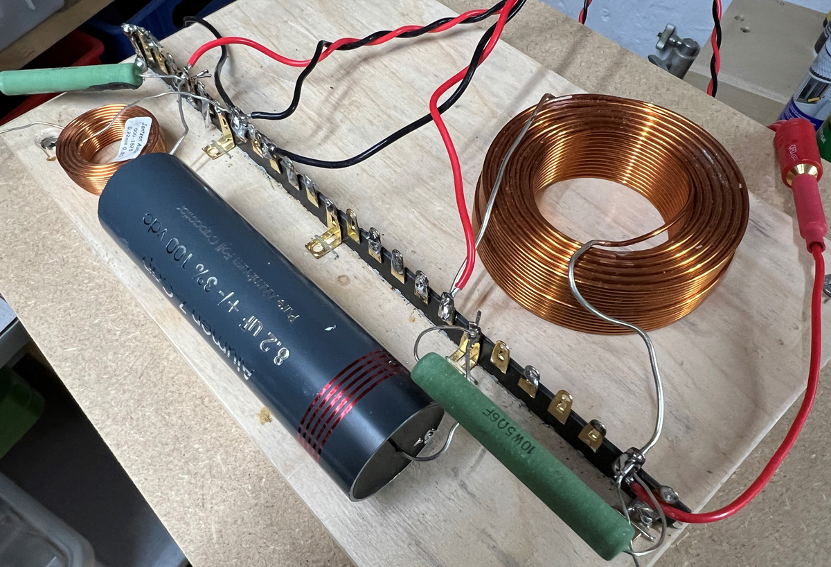
CROSSOVER-LAYOUT
BACK TO INDEX
Check this out before start making crossovers:
http://www.troelsgravesen.dk/tips.htm#CONSTRUCTION_OF_CROSSOVERS