|
DIY Loudspeakers: HOME INDEX UPDATES RESPONSE WHAT'S NEW |
|
|
Poor Man's Strad |
|
|
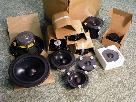
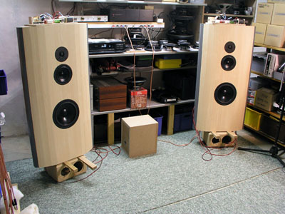
A box of new paper coned drivers from SEAS. The CA22RNX, MCA15RCY and MCA12RC. And soft domes: 27TDC and 27TFFC. Classic paper cones in new spider chassis. A box of opportunities - and many hours of work. It takes five minutes to order a box of drivers and you can spend months learning the strengths and weaknesses of each driver, trying to find the optimum points of crossover and the optimum crossover slopes for producing the best blends of sound that hopefully will integrate the drivers into a coherent and pleasant presentation. The number of options seems infinite. This speakers should have an Indian name and be called "Comes With a Room", because this is what wide baffled speakers o. They kind of bring in their own room. There's virtually no edge diffraction due to the wide baffle and the way these speakers recreate music in a room is special and to put it short: I like it! They can play strings, woodwinds and rock'n roll like few speakers of this size and from a 90 dB/2.8V sensitivity they do well with small amps. Read more about wide baffles and what they can do: http://www.troelsgravesen.dk/Acapella_WB.htm My wife had been attending a three-day course and when she came home and found the Poor Man's Strads in the livingroom she said: "These speakers aren't quite as big as the other wide (baffled) speakers, right?". "Indeed so, these are much, much smaller, actually almost one third the volume of the others" - I replied. So WAF seems relatively high and what helps is the very slim appearance when seen from the side. I have to say that my wife is a darling when it comes to speakers. For many months each year she lives with horrible looking MDF cabs in the livingroom - on their way to the workshop for further fine-tuning. Before ordering the drivers
I had one particular project in mind: A
classic 3-way
from an 8" bass driver, a 4" midrange driver
and a 1" soft dome. I wanted a 90 dB/2.8V
sensitivity, an easy load on the amplifier and I wanted
to measure how they would perform on a reasonably sized
wide baffle in order to make a Poor Man's Strad. This project has turned out much
better than expected and listening to a wide
range of recordings, CDs and vinyl, I actually wonder if
I should quit speaker building here. There's something
appealing about simplicity and this is an easy to build
speaker. From all the experiences of the past
constructions this one very much fulfills a wide range of demands: High
sensitivity, an easy load on the amplifier, a flat frequency response,
good phase integration between drivers, decent bass and a speedy, transient and
non-aggressive midrange. What more can you ask? Well, you
may get a slightly more neutral presentation from
magnesium or ceramic drivers, but most likely at the
expense of sensitivity. However, I would like to try a Accuton 5" driver for midrange, but some other time.
Here we go the good old paper way.
Basics:
Useful links:
FAQ: |
|
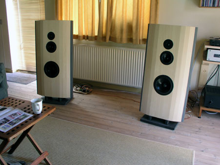
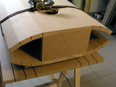
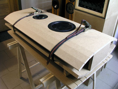
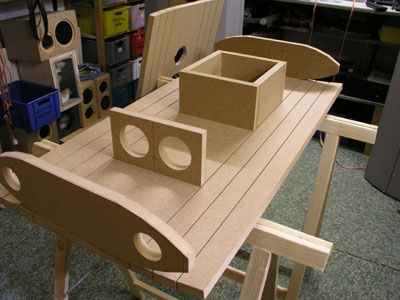
Vinyl
finish for the sake of photoshoot. Easy way of deciding
final cabinet design. The CA22RNX, MCA15RCY and 27TFFC
were set up in a small test cab and MDF side panels were
added by Gaffa tape to form an approx. 50 cm (W) x 105 cm
(H) curved front panel.
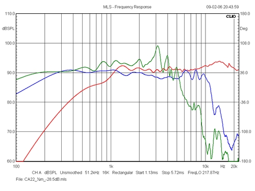
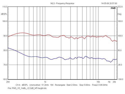
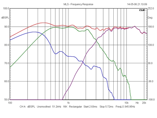
Left: Frequency response of all
drivers on wide curved baffle without crossover.
Green = bass, blue = mid, red = tweeter.
Something tells me we really are going
to get a sensitivity of at least 90 dB/2.8V and
the midrange seems to perform remarkably well.
Tweeter is basically flat from 1500 Hz to 20 kHz
and has the same little wrinkle around 17-18 kHz
as seen from the T25 tweeter. Not surprisingly as
they share the same type of diaphragm and lack of
polepiece damping. The CA22 has some cone
break-ups around 3, 4 and 5 kHz and I suspect a
somewhat resonant dust cap to be responsible for
this. Maybe I should "slice" the dust
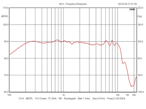
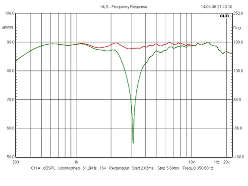
cap and see what happens. Right: MCA15RCY:
Not an everyday sight. Flat from 200 Hz to 5 kHz
and modest wrinkles from 5-10 kHz. Sensitivity =
90 dB/2.8V. This driver is flat over almost 5
octaves! Too good to be true. From these very promising initial
experiments a test cabinet was the only thing left to do.
But before this we need to think about the proper volume
of the cabinet for the bass driver. And we're going to
spend more time on this theme than usual.
It's always interesting
to see how your TS data measurements correlate with the
factory data. The "40Hz/4h" means second
measurements after the drivers had been given some heavy
40Hz massage for 4 hours. (Several weeks of use didn't
change this figure one single Hz).
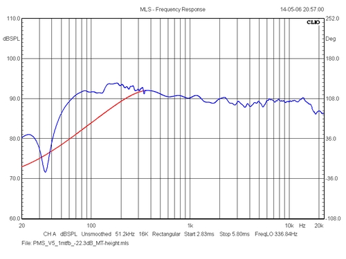
And here's the same thing
+ in-room response from planned placement of bass driver.
Minus 3 dB at 41.5 Hz ain't bad at all and there's bass -
and then there's bass. All depends. Due to the crossover
we lift the response above 100 Hz and room gain makes 1-2
dB below 100-125 Hz and we should get an overall
sensitivity around 91-92 dB. We'll see if the mid-driver
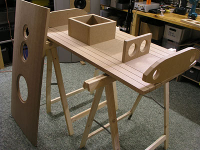
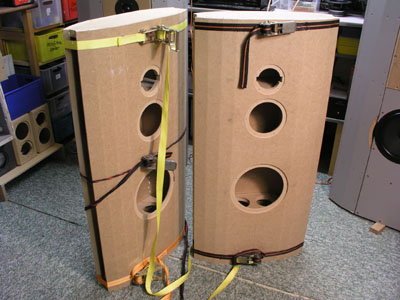
needs attenuation or not. Test cabinets:
After finishing the test cabs the actual volumes turned out to be 38 litres. A little less than intended, but the damping material will make the virtual volume somewhat bigger. What's seen above are the only drawings available. Two vents towards the floor will be placed on each of the “wings” and I'll use PVC tubing of 4.7 cm internal diameter. From a ~38 litres cab and a vent tuning of 38 Hz, the vents should be 80 mm long. I cut them 120 mm to enable some fine-tuning after driver installation. The tilt of the box is 5 degrees. Running the test cabs it's apparent they need more bracing. In particular the top panel and the panel above the tweeter have resonances. But these are only test cabs. Thanks to Tim Wilde, here's a link to a
Dutch website with lots of pics from constructing a
similar type cabinet: Mid cab vent A special section on the mid cab. The information has been here all the time but for some reason I've had the question 100 times about the mid cab vent. The mid
cabs are 4.3 litres net volume and the vent is a 40
x 70 mm PVC tube with an ID of 37 mm.
Actually this vent doesn't do much in the traditional way
of a vented box. I made it because the mid shouldn't be
in a closed box. And the mid cab vent is on the rear panel (I've had that one too :-))
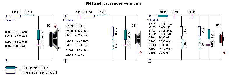
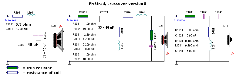
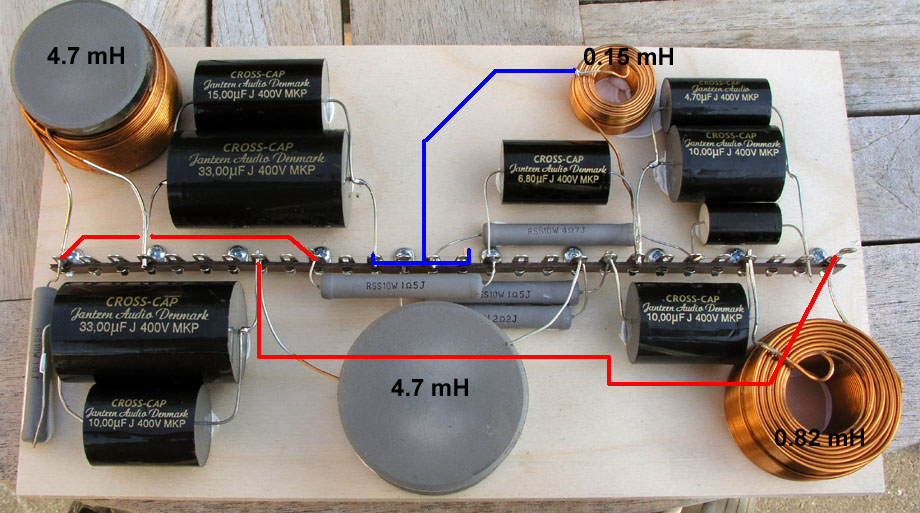
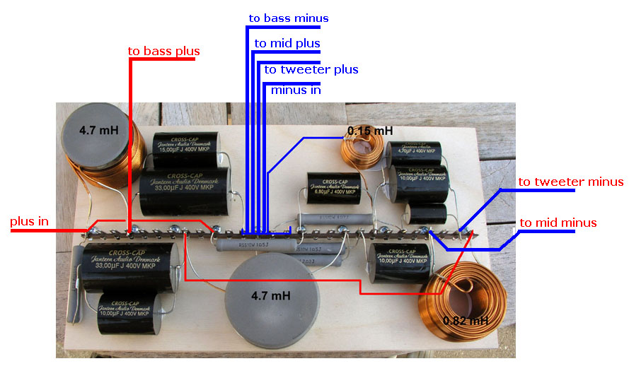
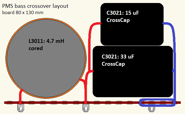
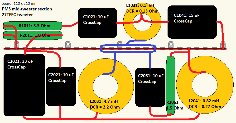
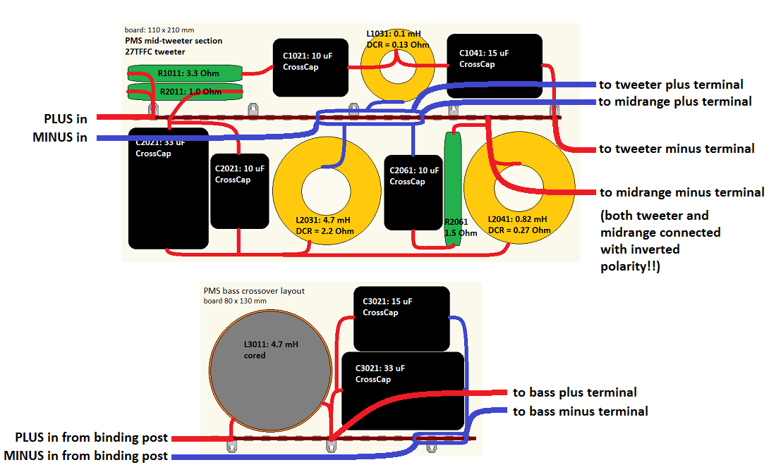
The final PMS
version 5 crossover
Coil L2031 supplied with the kit has DCR = 2.2 ohm, so you do not need to add any resistor (R2031)
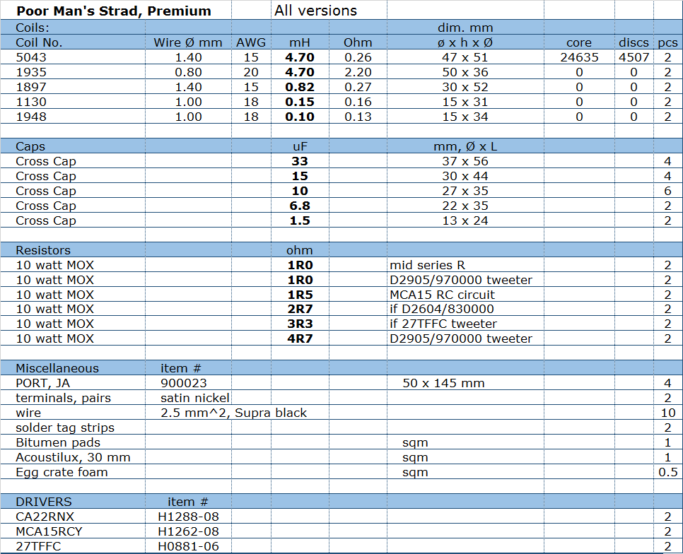
The list includes components for all three versions. The extra components for all versions comes at no extra cost (one small coil and 2 small caps).
All technical questions to All questions regarding purchase of
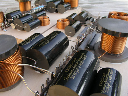
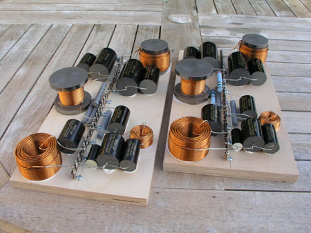
kits, please mail Jantzen Audio at Crossover construction
More layouts:
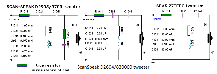
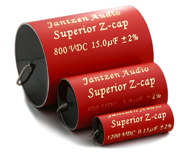
Standard P caps as seen here will only partly reveal what these drivers
can do. If you want to hear more, replace capacitors for midrange and
tweeters with Superior-Z caps. These are much bigger than CrossCaps and
you may have to split the mid and tweeter section in two.
Despite the crossover
being fairly simple, this part of the work was
considerably more trouble than expected. Maybe because
it’s simple... The bas-mid part was quickly done and
it ended up being an almost 12/12 dB giving the best
phase and sonic performance. Actually the bas-mid is very
close to a true L/R 12 dB crossover for 6 ohms drivers at
375 Hz (35 uF and 5 mH), although I reduce the Q of the
mid 4.7 mH coil by a 2R2 resistor. This first set-up was including
the 27TDC tweeter and despite an apparent high level of
transparency, there was something that didn’t sound
good. The 27TDC with its rigid, coated fabric diaphragm
needs the same cure as the T25 and a felt ring was added
to the centre polepiece and the terrible polyester foam
plug in the vent was replaced by some wool felt material.
This helped somewhat, but before doing more surgery on
the poor dome, the 27TDC was replaced by the 27TFFC and
things started going in the right direction. Everything
started sounding really good except for some vocals.
Vocals are the litmus test on any speaker. So back to the
LspCAD and some dozens simulations later it was finally
decided to take the point of crossover between the mid
and tweeter down to 3 kHz.
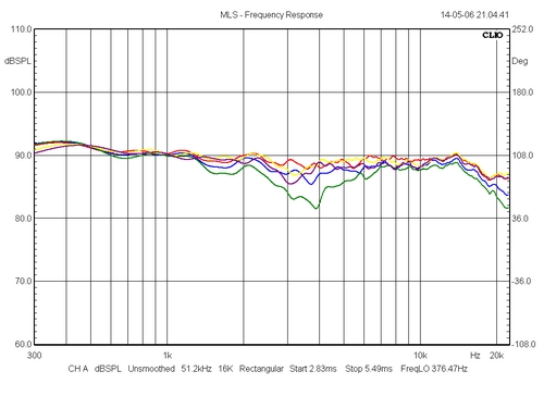
Left: Actual
measurement of frequency response at 1.0 m distance at MT
height and at 2.8V input. Sensitivity in the midrange is
around 90-91 dB. Not bad at a amplifier. Watch that
volume knob, these speakers can play really loud.
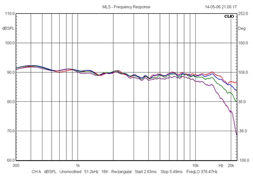
Left: Horizontal
dispersion: 0, 10, 20 and 30 deg. (Red, blue, green and
purple). This ensures a wide listening field with an even
sound dispersion.
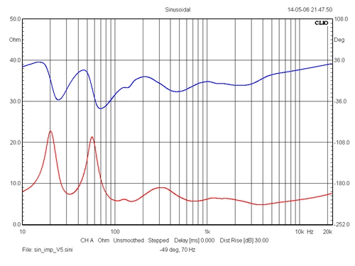
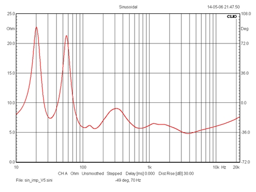
Left: Impedance
and phase from V5 crossover. Note the flat phase
performance. This is an easy load on the amplifier. The
phase at 70 Hz is -49 deg and the impedance here is 10
ohms. This is seen worse and from practical experience
this speaker can be played loud - very loud - without my
workshop solid state amp - a Rotel RB981 - running even
moderately hot.
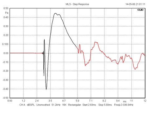
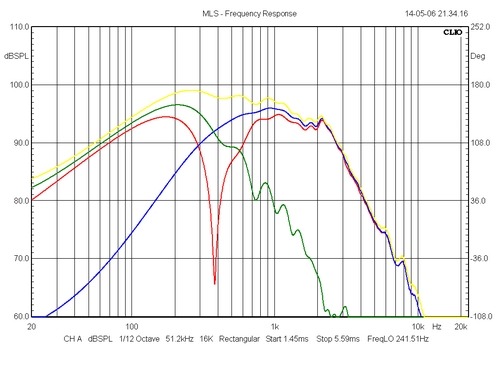
Left: Step response showing negative polarity of tweeter + mid and positive polarity of the bass. Right: Individual and summed response of drivers from the crossover.
Left: Mid and tweeter with opposite polarity. Right: Red = bass and mid with same polarity. Yellow is opposite polarity.
|