ScanSpeak
Revelator-66
Copyright 2022 © Troels Gravesen
Go to on this page:
DRIVERS
CROSSOVER
CABINET
WORKSHOP PICS
MEASUREMENTS
SPEAKER-KIT
CROSSOVER LAYOUT
It's been more than 15 years since I've done a Revelator 2-way like
this. This was the Sliced-Paper-95, and going through the files it is
clear I would make it differently today. Gone is the elaborate 4th
order crossover and in comes a better and simpler LR2 filter and proper
time-alignment.
Furthermore a new 18W/4531G01 is
available, albeit the 18W/4531G00 is still available. The difference is
primarily the cone, where the -G01 has some wood pulp mixed into the
cone material. TS data are almost the same and I wanted to try out this
change in cone composition.
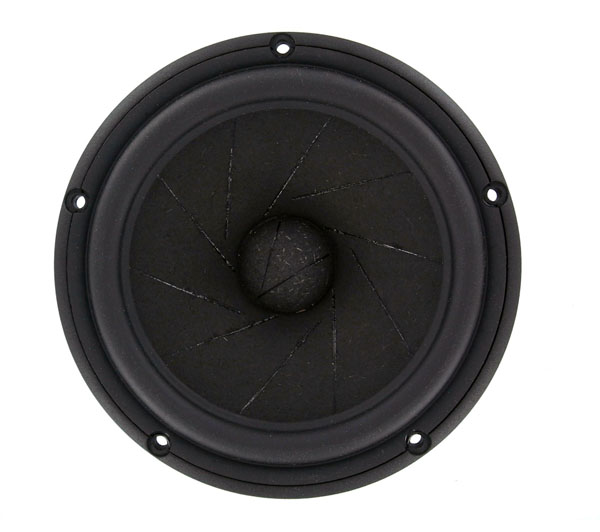
The Revelator series of drivers are unquestionably among the easiest
drivers on the market when it comes to crossovers. Smooth frequency
response all the way and no apparent cone break-ups due to the sliced
paper cone. I've seen the skilled ladies at ScanSpeak fill the cuts with
special glue. It takes time to do it right and apply the correct amount
of glue to each side of the cone.
I'm not sure when these Revelator drivers were introduced, but I guess
they are close to having a 20 years anniversary. I like products that
are well designed and stand the test of time. If it works, don't change
it unless some revolutionary technology pops up. Lately the D2008 and
D2010 tweeters had an update with neo magnets and new housing, yet the
same product as introduced some 50 years ago.
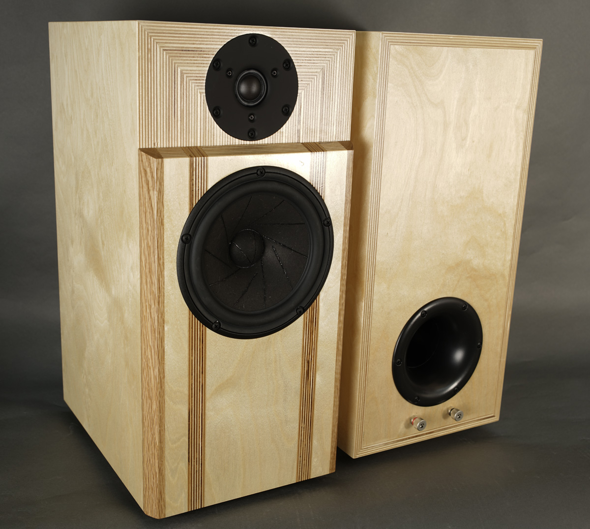
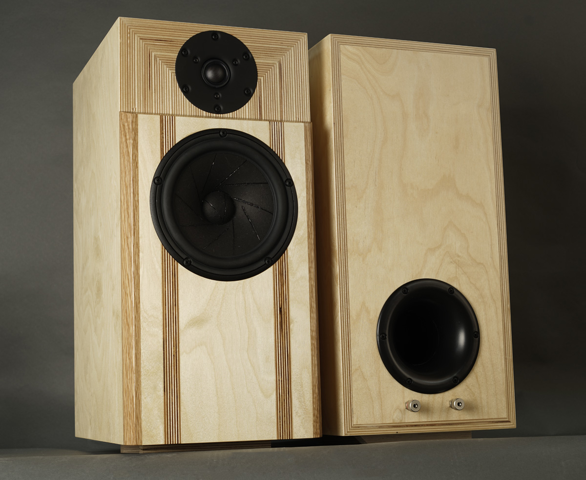
Basics:
3-driver speaker.
Dimensions: 24 x 33.5 x 50 cm, WxDxH.
System sensitivity: ~87 dB/2.8V/1 meter.
Impedance: 4-8 Ohms.
Power requirement: 20+ watts/channel.
Power handling: 100 watts.
Please
also read:
http://www.troelsgravesen.dk/power-handling.htm,
and remember any burned driver is a misused driver.
http://www.troelsgravesen.dk/tips.htm
http://www.troelsgravesen.dk/tips.htm#CONSTRUCTION_OF_CROSSOVERS
http://www.troelsgravesen.dk/crossovers.htm
http://www.troelsgravesen.dk/LCR-RC.htm
http://www.troelsgravesen.dk/Inverted-Polarity.htm
http://www.troelsgravesen.dk/choices.htm
http://www.troelsgravesen.dk/power-handling.htm
I'd forgotten how good an 18W Revelator is for the saxophone! My
goodness it goes loud without distressing to the ear and at the same
time doing deep bass and smooth upper-mid before it hands over to the
tweeter. I guess the lack of break-up modes higher up the treble range
is responsible for the overall smooth sound. This 18W driver is truly
the easiest 7" on the marked when it comes to crossover. And this not at
the expense of resolution! As can be seen a simple 2nd order topology
with no notch filters or anything to correct irregularities in frequency
response. The same thing as seen for the 15M/8631G00 use in my
Revelator-851s.
I'd forgotten the sound of the Illuminator-71, which is almost identical
to this one except for midbass driver, but I suspect this Rev-66 equals
the sound - and at some 300 EUR less. For the size, deep bass, and I
suspect the use of the not so cheap 70 mm largely flared port, the same
used in the Illuminator-71, is responsible for the great bass.
This stand-mount truly finishes my ambition of having a wide range of
Revelator based speakers from small stand-mounts to large 3-ways.
I liked my Illuminator-71s so much I'm going to build another pair
to keep. When done I'll come back to comparison with this Revelator-66.
I suspect the differences to be small - if any more than taste and
preoccupation.
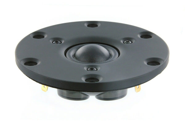
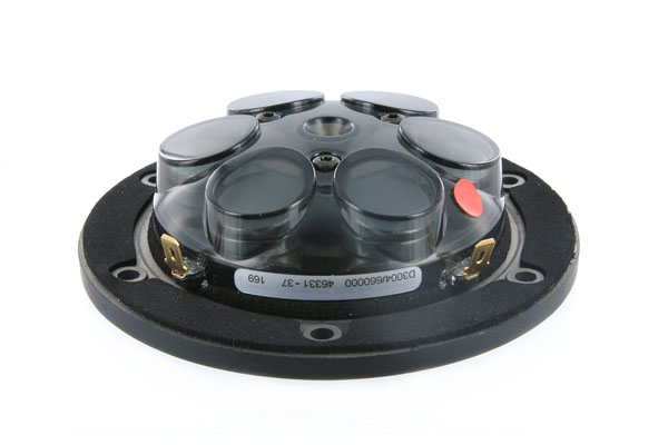
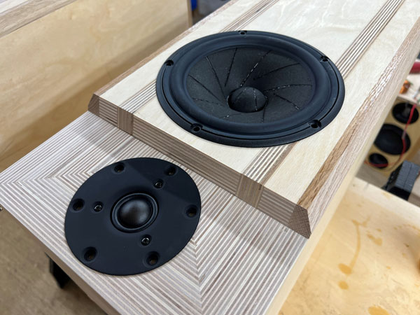
D3004/6600000 tweeter.
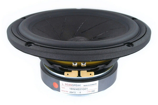
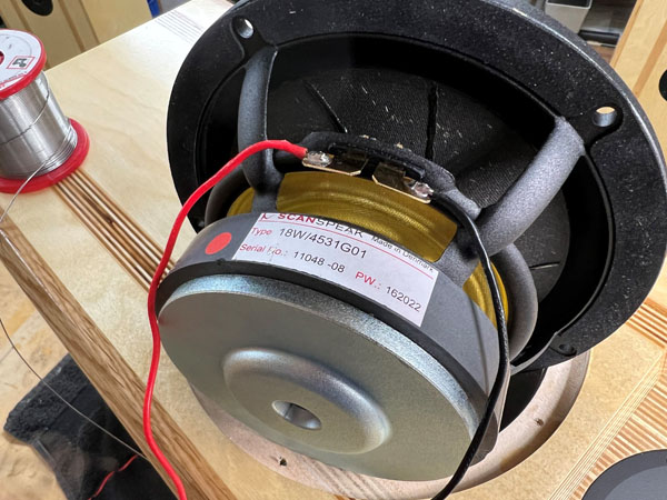
18W/4531G01 midbass driver.
Download specs here: D3004/660000 18W/4531G01
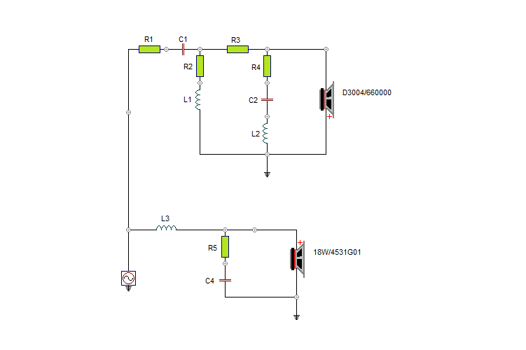
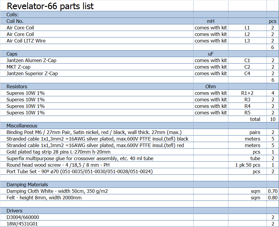
The crossover is a straight 2nd order LR2 topology. We need to linearise
the impedance of the tweeter, hence R4+C2/3+L2 to do so. Otherwise no
special ingredients. Tweaking the ratio of R1 and R3 for attenuation was
part of the job. I matters where we add most of the necessary tweeter
attenuation to reach target roll-off.
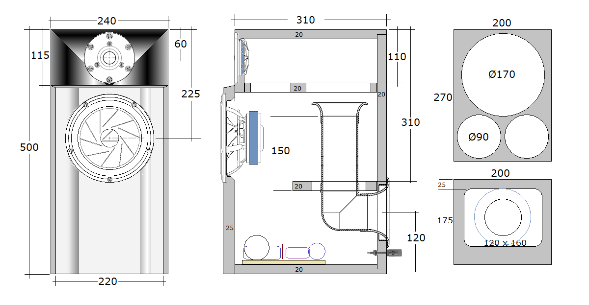
Cabinets were made from 20 mm Baltic birch. The lower brace only makes a
little more than half the width allowing placement of crossover at
bottom of cabinet through the midbass driver hole.
The midbass front panel was chamfered 30 deg. to the sides and 20 deg.
to the top. Chamfering the midbass panel is optional, but I do at least
suggest rounding the edge towards the tweeter, say r = 5-6 mm.
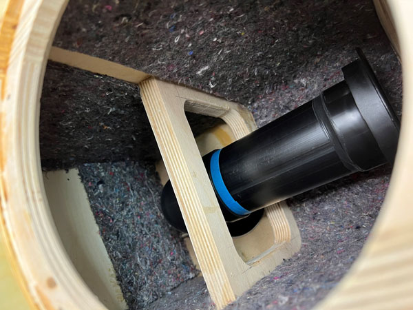
Cut straight port tube to 150 mm. Assemble port with Superfix.
Well, not a whole lot to show here. The cabs are basically the same as Illuminator-71, so look here.
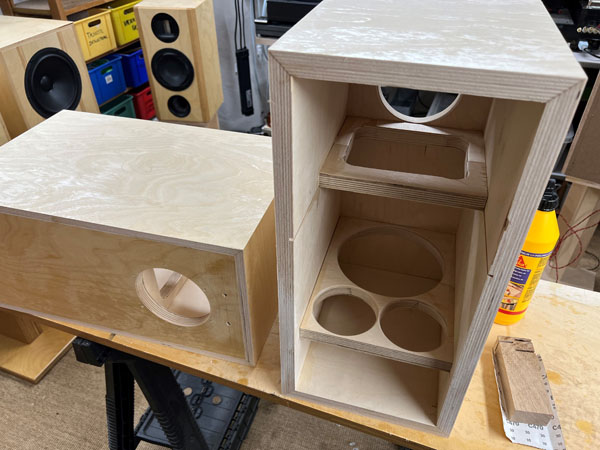
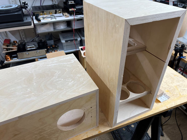
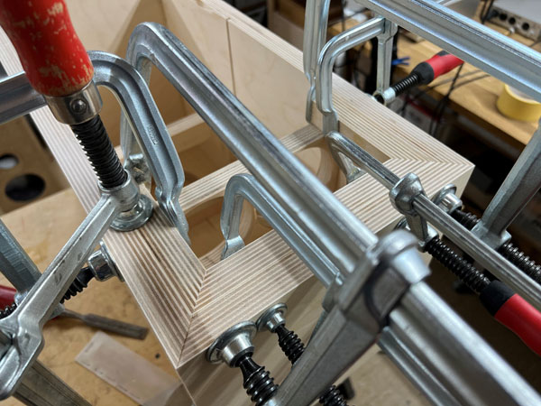
Cabinets in the rough after gluing.
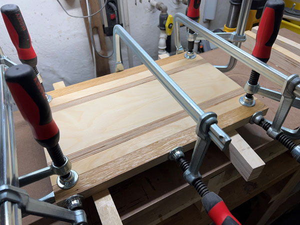
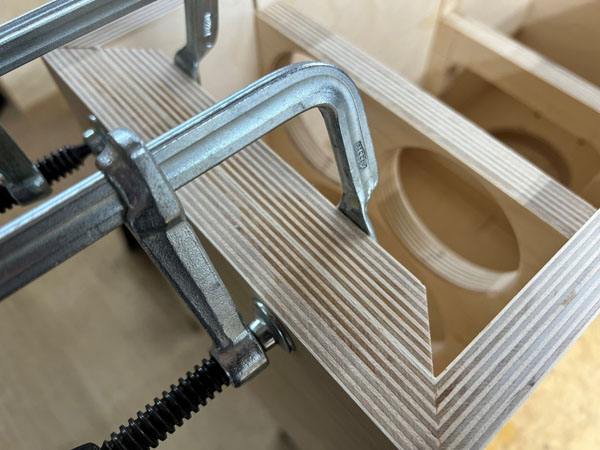
Gluing front panels.
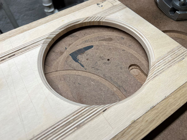
Making the tweeter panel.
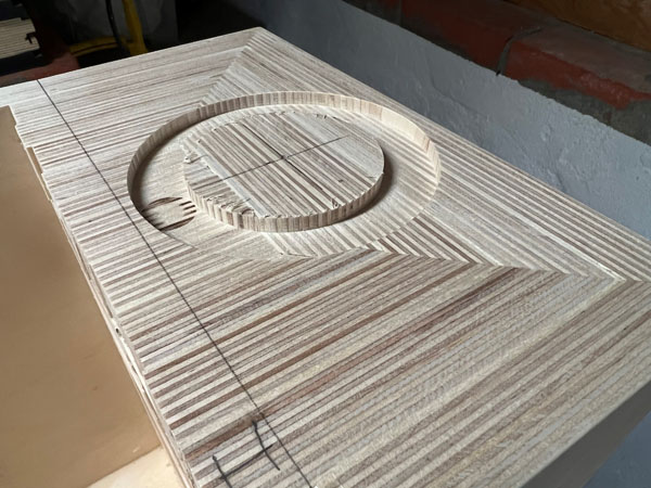
Routing for tweeter and testing drivers in
final rebates.
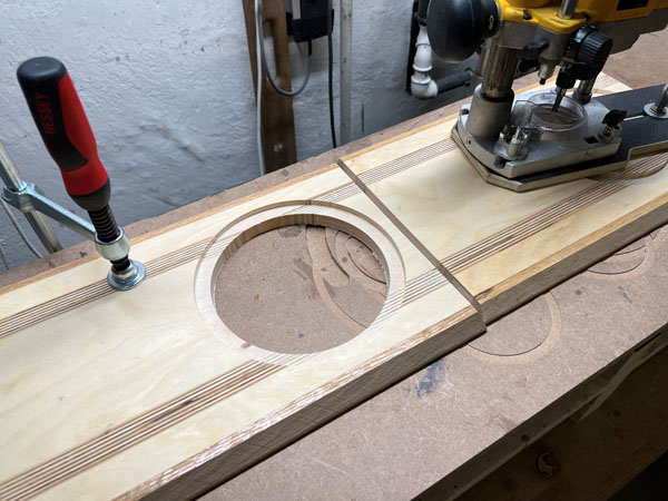
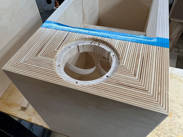
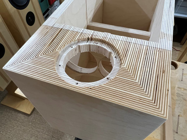
Routing front panel for midbass. Chamfer rear
slightly, 45 deg. to some 5-7 mm depth.
With speaker like these I add lacquer to the
tweeter section before gluing the midbass panel. Just easier than doing
it after.
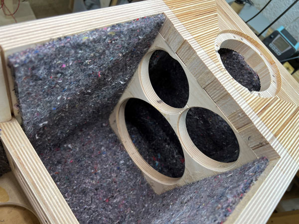
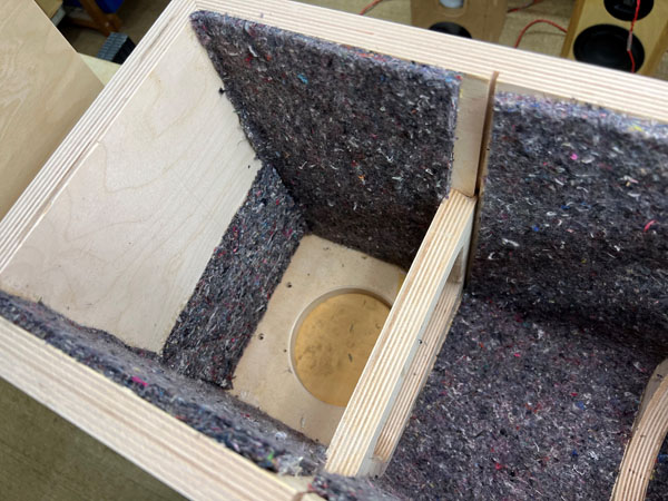
Felt damping added. Leave open area at bottom
for placement of crossover.
I used 0.67 m^2. 0.75 m^2 comes with kit.
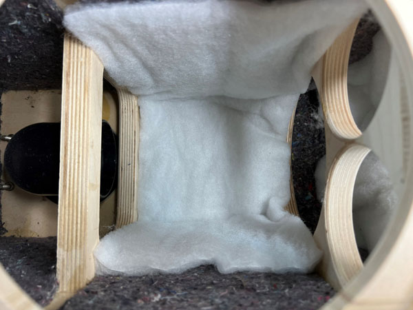
Left: Fold one piece of 20 x 50 cm acoustilux and place at top behind
tweeter.
Right: Ad one piece of 18 x 50 cm behind midbass driver.
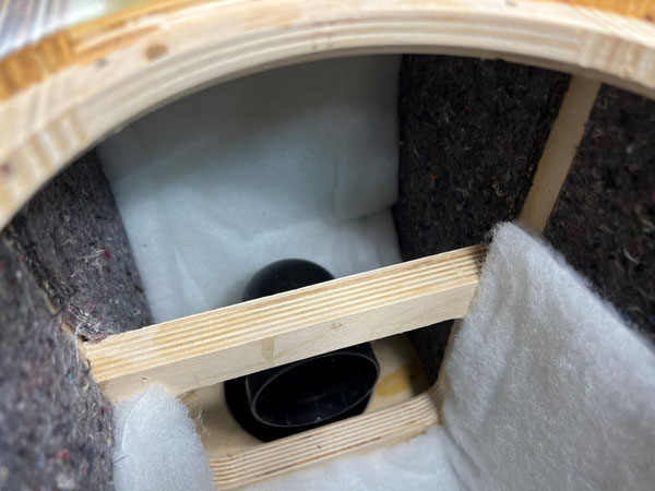
Left: Fold one piece of 20 x 50 cm acoustilux and place at bottom above
crossover.
Right: Just to show port in place. Disregard the blue tape, just a
temporary arrangement before finally glued in place.(Cut straight port
tube to 150 mm length)
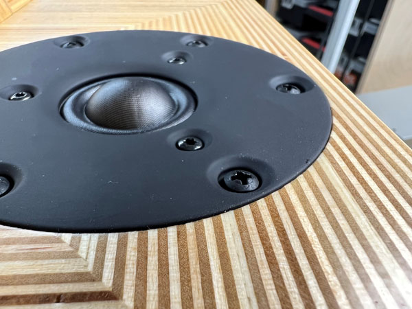
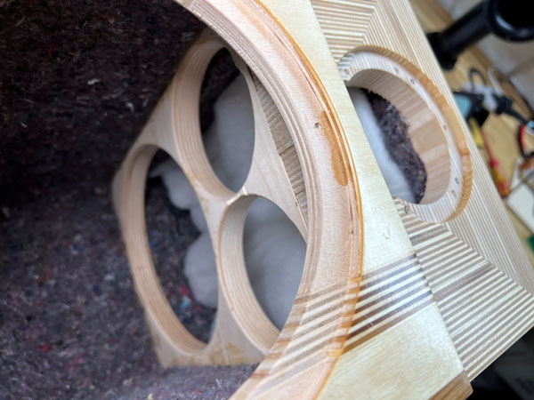
D3004/660000 in place. Route to ~5.7 mm depth
for flush mounting.
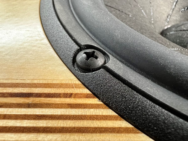
Left: For the 18W driver I make the rebate 6.5 mm to have the edge of the
frame flush with the front panel.
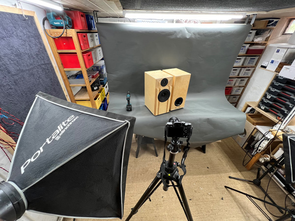
Right: The photoshoot :-)
A few comments on
MEASUREMENTS before you start interpreting the readings below.
First of all, if we think measurements will
tell us how a speaker sounds, we're wrong. The perception of sound is
way too subjective to be reflected in any measurements we can perform. A
loudspeaker system is meant to give us a satisfying idea of an acoustic
event and for some people a pair of 5 USD ear-plugs are enough, others
spend 200 kUSD on a truly full-range pair of speakers - and the latter
may not be happier than the former.
Measurements may give us an idea of tonal balance of a system, i.e. too
much or too little energy in certain areas, although dispersion
characteristics play a vital role here. A two-way 7+1 and a three-way
7+4+1 may display similar horizontal dispersion, yet sound very
different. Measurements may tell us about bass extension if far-field
measurements are merged with near-field measurements. In addition to
this, ports may contribute to bass extension. Most of we diy'ers do not
have access to an anechoic room for full-range measurements from
20-20000 Hz.
What cannot be seen is what kind of bass performance we get in a given
room. Bass performance is highly dependent on in-room placement of your
speaker and the same speaker can be boomy in one place and lean in
another. Actual SPL level at 1 meter distance and 2.8V input is useful
for en estimate of system sensitivity and combined with the impedance
profile may give an idea of how powerful an amplifier is needed to drive
the speaker to adequate levels.
What measurements do not tell is the very sound of the speaker unless
displaying serious linear distortion. The level of transparency, the
ability to resolve micro-details, the "speed" of the bass, etc., cannot
be derived from these data. Distortion measurements rarely tell much
unless seriously bad, and most modern drivers display low distortion
within their specified operating range.
Many people put way too much into these graphs and my comments here are
only meant as warning against over-interpretation. There are more to
good sound than what can be extracted from a few graphs. Every graph
needs interpretation in terms of what it means sonically and how it
impacts our choice of mating drivers, cabinet and crossover design.
What measurements certainly do not tell is the sonic signature of the
speaker, because speaker cones made from polypropylene, aluminum,
Kevlar, paper, glass fiber, carbon fiber, magnesium, ceramics or even
diamonds all have their way of adding spices to the stew. Nor do
measurements tell what impact the quality of the crossover components
add to the sound, from state of the art components to the cheapest of
coils and caps, they all measure the same if values are correct, yet
sound very different.
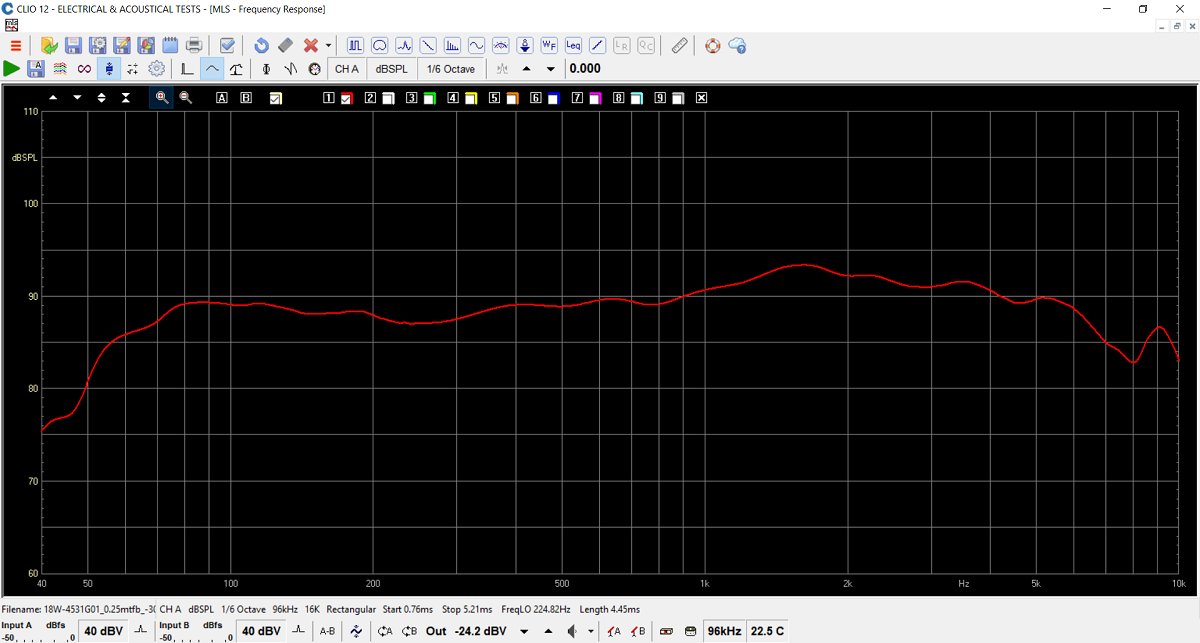
Frequency response of 18W/4531G01 on actual
baffle, merged with nearfield response at 250 Hz.
This calls for simple crossovers! Smooth all the way with no rubber
surround resonances in the 800-1000 Hz range, so vital for the midrange.
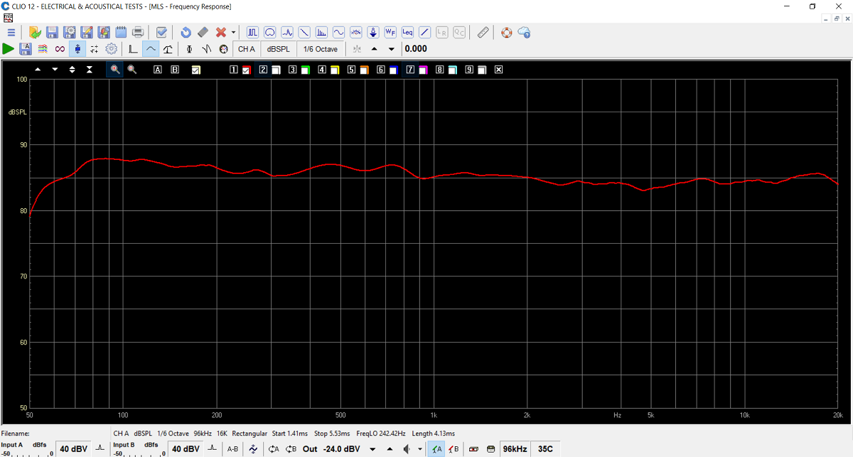
System frequency response merged with woofer
near-field response at 300 Hz. Port contribution not included.
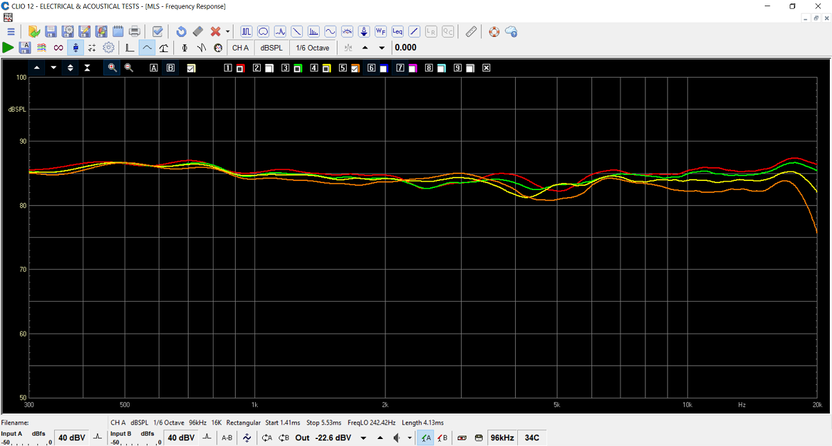
Response at 0, 10, 20 and 30 deg. off axis,
red/green/yellow and orange.
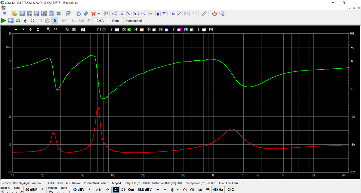 Final
system impedance. Minimum 4 Ohms @ 37/150 Hz. Green: Electrical phase.
Final
system impedance. Minimum 4 Ohms @ 37/150 Hz. Green: Electrical phase.
All kit and component prices may be subject to change and are always to be confirmed by Jantzen Audio Denmark.
Kits can always be bought with/without drivers, or some of the drivers.
Download Complete Kit Sale Presentations:
![]()
All technical questions to troels.gravesen@hotmail.com
All questions regarding purchase of kits, please mail Jantzen Audio at contact@jantzen-audio.com
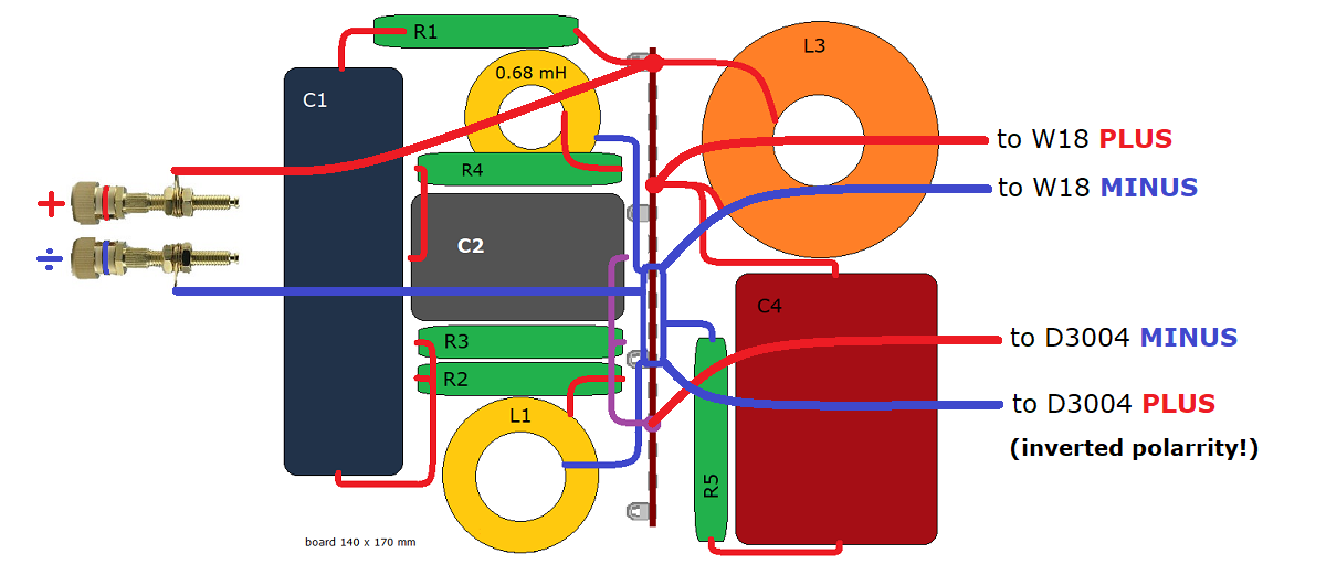
CROSSOVER-LAYOUT
BACK TO INDEX
Check this out before making the crossovers:
http://www.troelsgravesen.dk/tips.htm#CONSTRUCTION_OF_CROSSOVERS
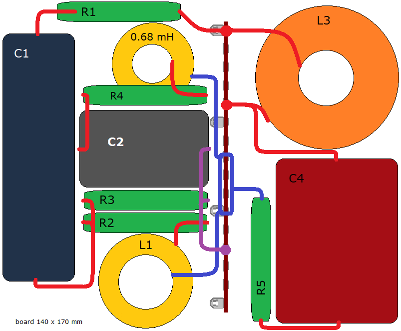
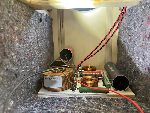
Crossover layout.
Pay notice C3 is gone and replaced by one MKT Z-cap.

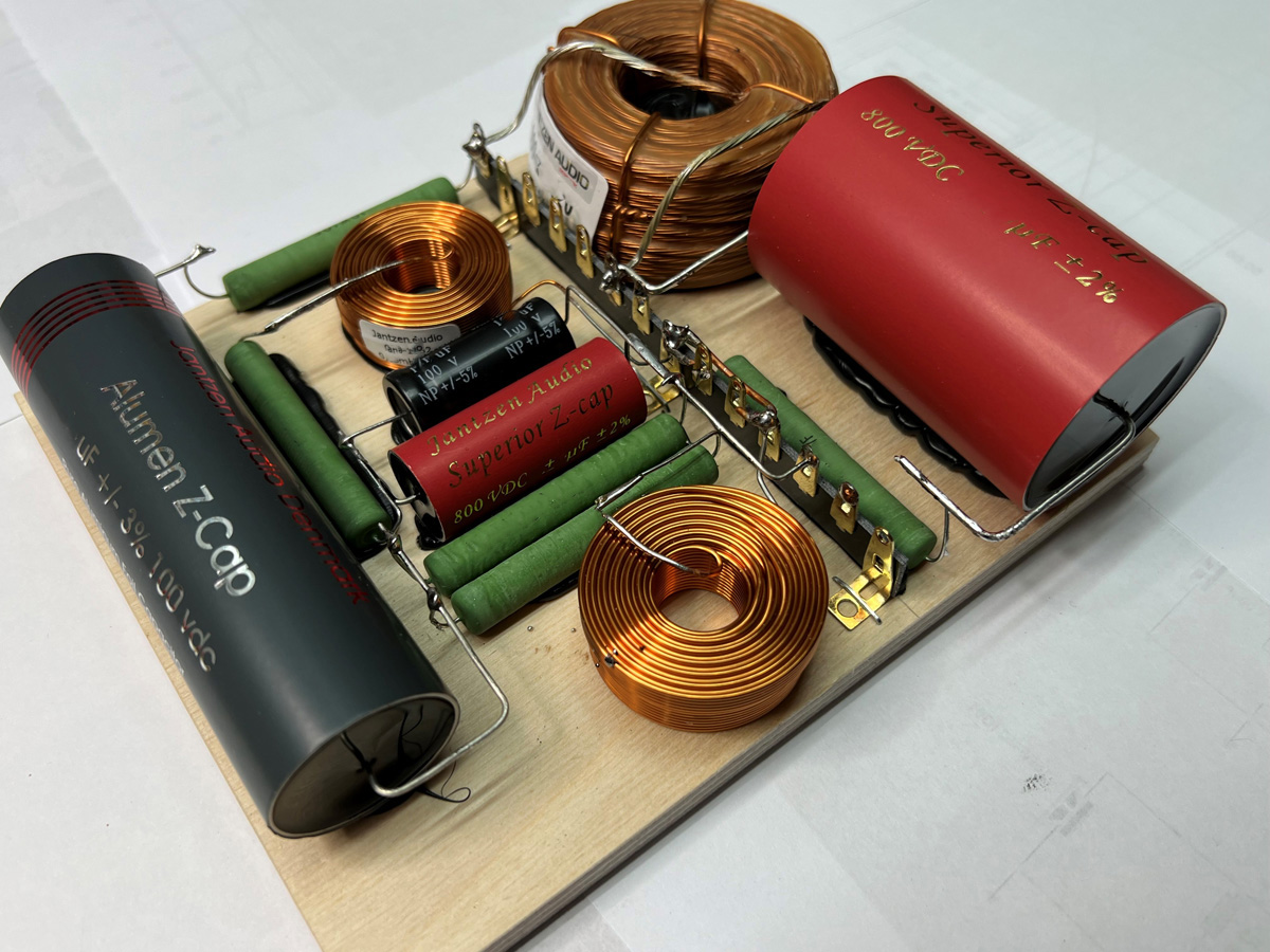
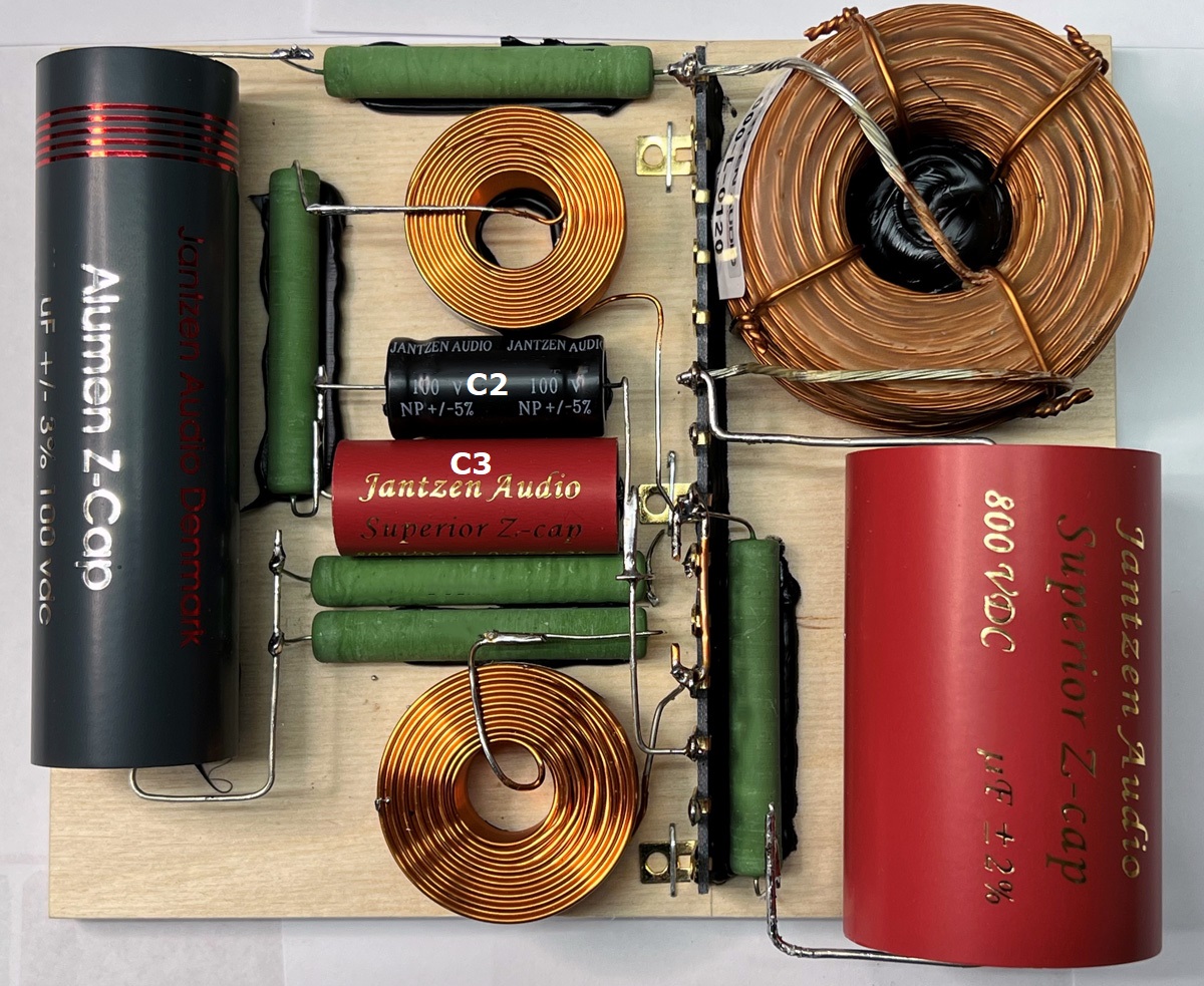
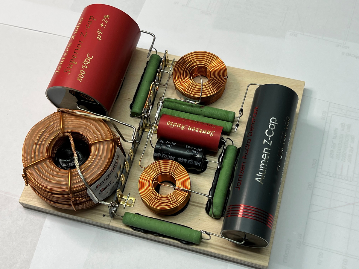
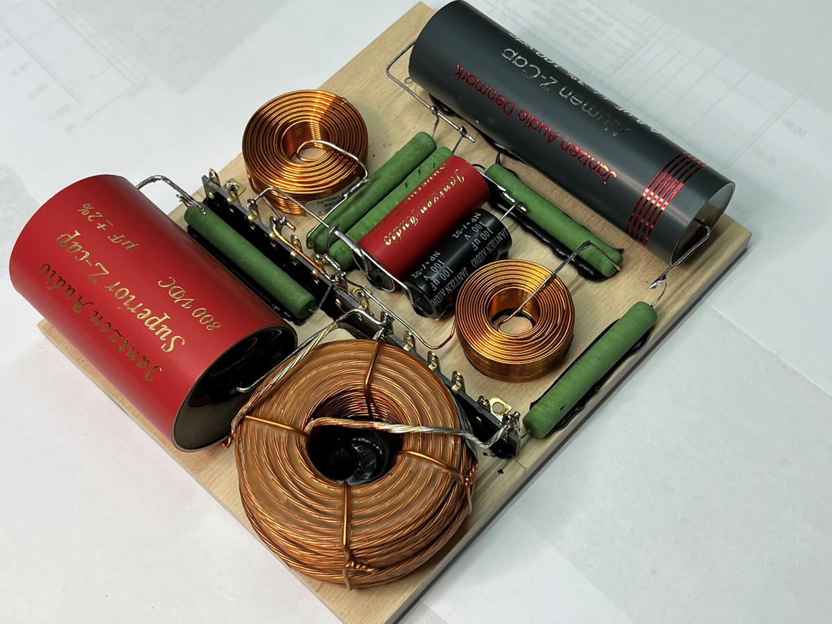
The crossover from various angles. Click images to view large.
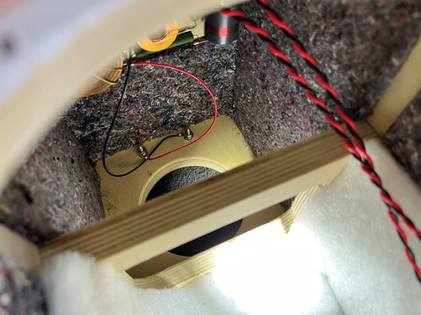
Crossover placed at bottom of cabinet. Fasten with two screws.
Disregard double capacitor for C4. Prototype thing. One capacitor for C4
in kit.