|
The article here was meant to be
a quick review of the ScanSpeak 18WU/8741T00 driver paired with either
7100 or 6600 tweeters. A two-way from said driver and the 6600 tweeter
was quickly in place and I started on the implementation of the 7100
tweeter. Another two-way in a few days. My simulation software is a
great tool - and toy, and the more I played around, the more options
became available, thus numerous crossovers were made for evaluation,
each time taking performance a little further. Every time the "quick'n
dirty" turned out not to reveal the full potential of the
drivers. I used to think 3-ways were more trouble than two-ways, but
now it seems to be the other way around. Due to the limitations of a
two-way, care must be taken in overall balancing of the system. It
takes time adjusting to the limited sound stage from a small speaker,
being used to DTQWT and Jenzen speakers. The traditional 6+1 really can't play
very loud
and the weight of the bottom end is missing. Anyway, below the best - to my ears - is presented. No 6600
version will be presented.
Illumination
can mean enlightenment, insight, etc., and this is probably what
the ScanSpeak guys were thinking of when designing these speaker
drivers. A driver that would enable us to dig further into our
recordings and discover new details previously hidden by flexing cones
that may provide an overall smooth frequency response, but never
really deliver the final micro details.
Former top of the range drivers from ScanSpeak featured sliced paper
cones, the Revelator series. Revelator drivers are a dream when
it comes to crossovers. Due to an inherent smooth frequency response
they're easy when it comes to crossovers, the heart
of the speaker. It goes without saying that slicing a paper cone and
gluing it together again with flexible glue comes at a price. We may
have solved the problem of damping resonance - mechanically - but we
may have lost the ability to reproduce micro detail.
Getting more detail we need more rigid cones like ceramics or metal
cones. The price to pay is usually serious resonance at higher
frequencies with subsequent need for notch filters or high-sloped
filters, e.g. magnesium cones.
A compromise between soft
cones and hard cones are sandwich cones used by e.g. Eton and
AudioTechnology. Eton favors the hexacone technology, while
AudioTecnology has adopted a sandwich of paper-foam-paper, but only
for bass drivers. Both
technologies work well and deliver pistonic movement within their
operating range. Another driver (cone) that impressed me was the Chario Sonnet
midbass, which is actually a Rohacell
cone. Rohacell is a foam material made from polymethacrylimide and
the trick is to make a sandwich of two layers of plastic polymer with
the Rohacell foam in between; rigid, light-weight and with high
internal damping. Trouble part is
designing cone geometry so that we also get a smooth frequency response.
ScanSpeak decided to stick to
paper, but here we have two identical ribbed paper cones glued
together by something. What this "something"
is remains a secret, possible only glue. The result is a rather rigid
cone helped by the curvilinear cone geometry. And the dust cap - the
inevitable - and troublesome - dust cap is not just a standard hard
pressed paper dome, but made from a pulp similar to the cone
itself. Whether the dust cap is a sandwich I can't tell. I guess
it is.
Next they designed a low-reflecting magnet system that would at least
divert rear energy away from the driver and not bounce back into the
cone, thus a fancy neodym magnet system with a sloped upper pole piece
allowing a deep magnetic gap of 20 mm! The voice coil height is only 8
mm, thus a linear excursion of +/- 9 mm according to SS specs. 9 mm
will take the voice coil out of the magnet gap it seems. What we have here is an
under-hung voice coil contrary to most speakers fitted with a short
magnet gap and a long voice coil, the over-hung system. The benefit
from this is arguable, but we don't have a coil outside the
magnet gap picking up eddy current from the magnet gap. At least
that's what we learn about underhung voice coils. There have been made
many great speakers over the years without symmetric drive and
with overhung voice coils and to my knowledge we have never
seen distortion measurements from two otherwise identical drivers
having these features.
What I leaned
from Per Skaaning of AudioTechnology is that an under-hung system
usually provides a slightly concave frequency response contrary to an
over-hung system delivering a convex frequency response. It looks like
this:

Looking at the frequency
response of the 18WU drivers suggest there is something to this
generalisation, a slightly recessed midband compared to the response
at e.g. 100 Hz and 1 kHz.
I've been hesitant to dig into the Illuminator series due to three
reasons: Higher price (compared to Revelator), lower efficiency and a ragged frequency
response. These are good reasons, aren't they?
If we look at 18W/8545-00, 18W/8531G00 and 18WU/8741T00 we have a
claimed sensitivity (2.8V) of 88 dB, 87 dB and 85.4 dB respectively,
the low efficiency of 18WU partly due to underhung voice coil. To my thinking this is the wrong way. What we get is lower bass from
smaller enclosures at the expense of efficiency and there may be good
marketing rationales for this and I fully acknowledge the need for
black bottom line figures rather than producing items a few people
love, but nobody buys.
So, the Illuminator series has stayed put until someone offered me a
pair of 8 ohms 18WU for loan. I had just acquired a pair of 6600 and 7100
domes, so the obvious thing to do was to set up a simple two-way from
these tweeters and the 18WU/8741T00 drivers in my 21 liter test
cabs, actually ready-made cabs from PartsExpress, type 302-730, 0.75
cubic feet - for you over there.
Useful links (Please read before writing!):
http://www.troelsgravesen.dk/tips.htm
http://www.troelsgravesen.dk/crossovers.htm
http://www.troelsgravesen.dk/LCR-RC.htm
FAQ (Please read before writing!):
You cannot change cabinet front panel dimensions and drivers' placement
without needing a new crossover - and I cannot help.
You cannot use any other drivers with the crossover shown here.
Please read these files before e-maling:
http://www.troelsgravesen.dk/crossovers.htm
http://www.troelsgravesen.dk/choices.htm
The
Drivers
BACK
TO TOP
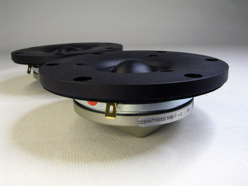
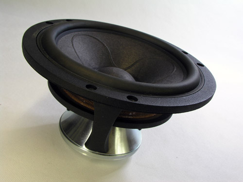
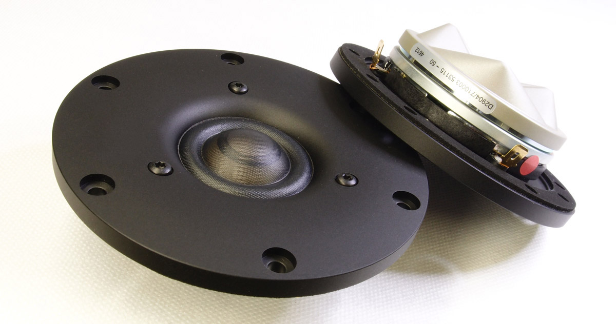
D2904/710003
tweeters. Illuminator 18WU/8741-T00
Click to view data sheet. Click images to view large.
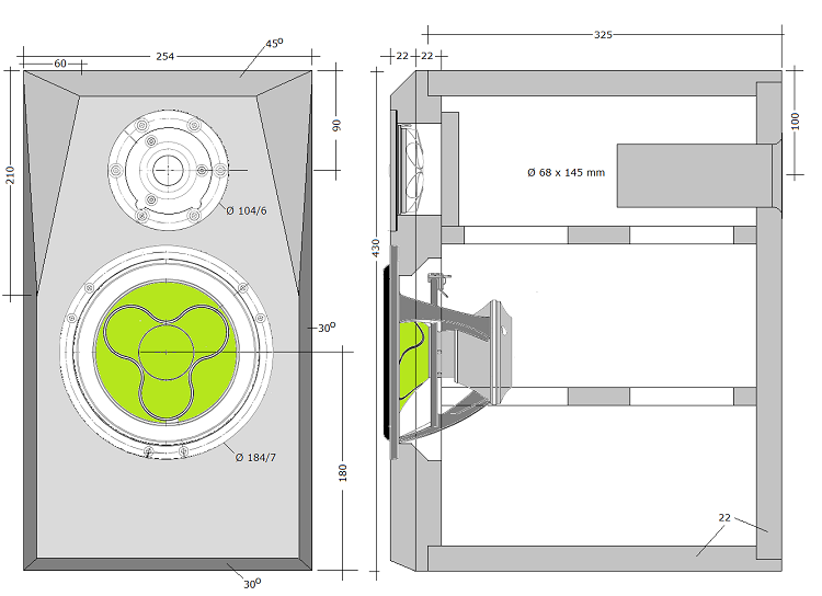
Cabinet
BACK
TO TOP
 Click image to view
large.
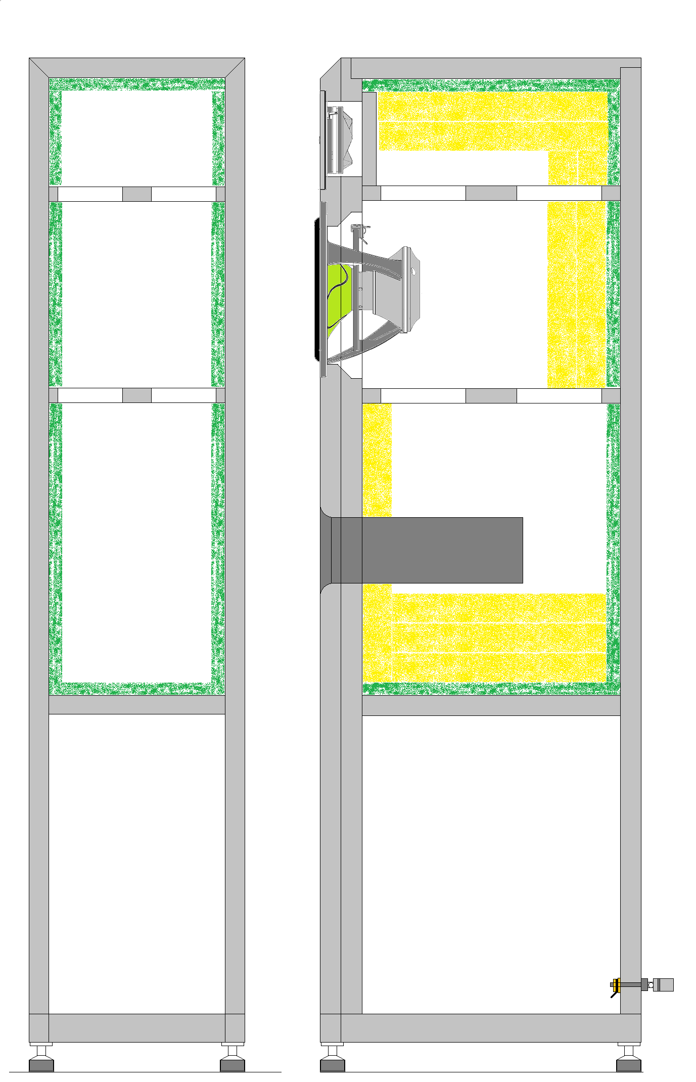
I suggest 20 mm
Baltic birch for cabinet.
Place bracing across cabinet height as seen on sketch and make curved
cutout for midbass driver. Make front panel from two layers of 19-22 mm MDF. Make sure you
chamfer midbass driver hole as seen on sketch.
Place tweeter
crossover at bottom and make sure it can get through the bass driver
hole - or make a hatch at the rear side. With super caps and wax coils
you need to make sure you have sufficient space. The bass crossover is
placed on rear panel between the two braces.
I strongly suggest
attaching the rear panel with screws for easy access to the crossover.
Small cabs are always a challenge when it comes to space for the
crossover. Cabinet
damping: Please check: Cabinet damping
and this one: QUATTRO.htm
for ideas. Damping materials included in kit. Felt
for port: Cut 13 mm felt to 100 x ~195 mm, slightly trapezoid like
seen on photo: 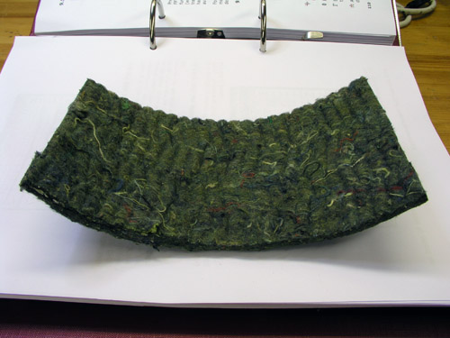
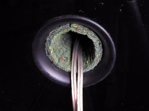
I've recently seen this trick launched
as the eight wonder of the world by Sonus Faber; it's called
"Stealth Reflex", there you go!
This was used
by Spendor four decades ago.
From
SF website:
The "Stealth Reflex Port" is Sonus Faber's patented solution
for the realization of a para-aperiodic enclosure ventilation system.
The properties of this system allows for deep, extended bass with the
same or less cabinet volume. In addition, it has all the advantages of
conventional ports but eliminates the inherent "chuffing"
sound completely.
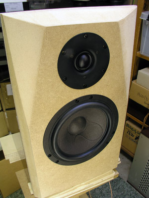
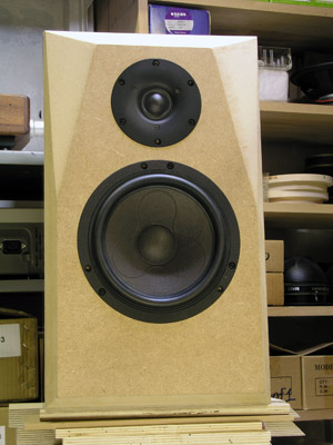
Test cab front panels.
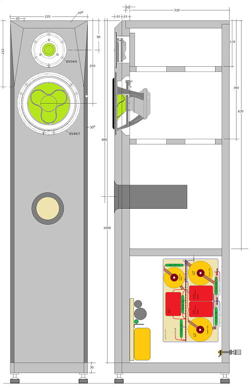
FLOORSTANDER
As mentioned above, you
can make a floorstander from this construction with a 22 cm wide front
panel. Use 22 mm MDF throughout. Maintain top chamfering of front
panel, reduce side chamfering to 45 mm
width at top. Cab height is 100 cm + 30 mm base plate. Use
feet or spikes to make top panel some 105 cm above floor level.
30 liter cab volume is close to ideal for the 18WU/8741T00 driver
making F3 = 37 Hz. Port tuning = 35 Hz, Use 68 x 220 mm port (Jantzen
#900018). And no felt in this port!
Cabinet dimensions from 22 mm MDF: 220 mm width x 1000 mm
height x 344 mm depth, all external dimensions.
The rationale for the deep box is to reduce early reflections. Now we
have a low-reflection speaker driver there's no need to spoil the good work of
ScanSpeak but adding a rear panel up against its back.

Click images to view large.
Check out here
for damping. Use 13 mm grey felt on all internal panels, except front
panel. Place two layers of 30 mm acoustilux on top and rear panel
behind drivers, not behind port. Place three layers of 30 mm acoustilux
below port.
The Sound
BACK
TO TOP What
struck me the most listening for the first time was the bass response.
Not since the unfortunate 2.5 clone had I heard such low bass from a
6" driver, and this coming from a meager 21 liter. Quite
impressive although you should not expect a full-bodied sound like a
Jenzen speaker, which were in place when these were taken to the
living room.
Lots of low-level detail too thanks to the rigid cone
and high mechanical Q. These rigid sandwich
cones indeed do reveal a few details former Revelators may be short
of at higher SPLs. But don't overestimate a "6+1"
system, there are limits to how much power it takes. As-is they
deliver a smooth midrange with good upper-mid integration and should
these speaker sound harsh, look at your gear - or you're playing too
loud. Maybe a bold statement, but I'll stick my neck out.
And BTW: 6" or 7". There seems to be some inflation in
driver size as SS really market these as 7" drivers. They are
big 6" drivers with a membrane area of 154 cm2.
Usually a 6" makes 130-140 cm2. Most 8" drivers
make 220 cm2. So, I guess a 7" should manage something
in the range of 170-180 cm2, like the Audio Technology 6I52
having 174 cm2. The Accutons are marketed as 7" driver
and really only makes 132 cm2 and are nowhere near a
7" driver, rather a small 6" driver. Anyway...
This 21 liter stand-mount will challenge any 30 liter floor-stander
and should your spouse find 21 liter on a stand less intrusive on
interior decor compared to a 30 liter floor-stander, this may may be an
option for getting some good hifi. And while we're at it, you can extend the cabinet to
some 28-32 liter and get even lower bass. Keep panel width and driver
placement with regard to top of cabinet.
As always, tweeter level needs some
experimentation, thus a range of series resistors added to the
crossover kit. It MUST be tried to suit room-placement, room damping,
listening distance, front-end gear and not least personal preference.
Taste cannot be argued and if you want a ruler flat response at 2-3
meter listening distance, be my guest. Due to the low point of
crossover, dispersion is significant in lower-treble range and from a
flat tuning it can be too much - and to my ears, just doesn't sound
natural. We badly miss the tone controls of former line-stages to
balance the sound in our rooms and the result may be endless tests of
gear and cables to find a proper balance. Quite often a 1 USD resistor
is all it takes to tame a too aggressive treble level.
Crossover
BACK
TO TOP
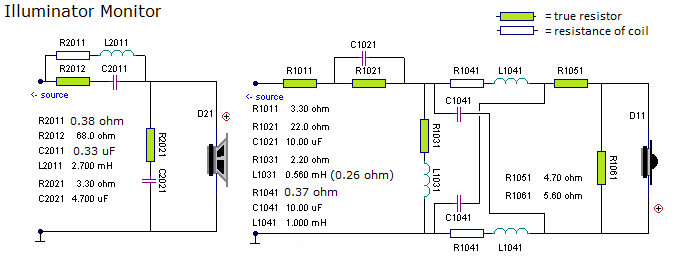
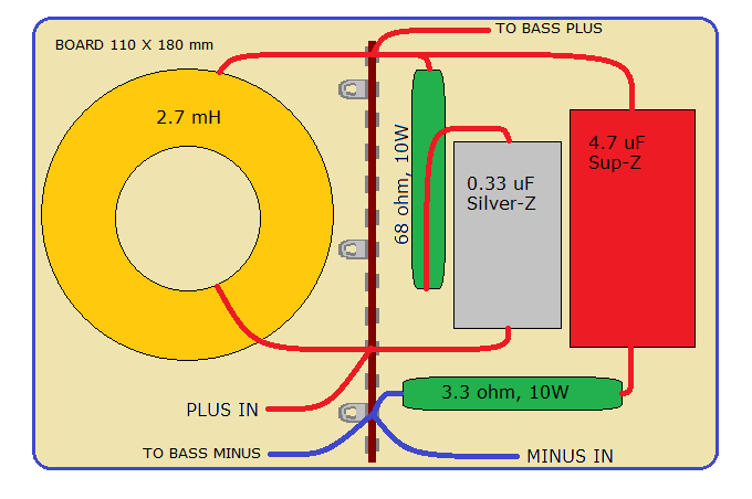
The crossover follows an
LR2 topology. For the bass an RC circuit across series coil provides
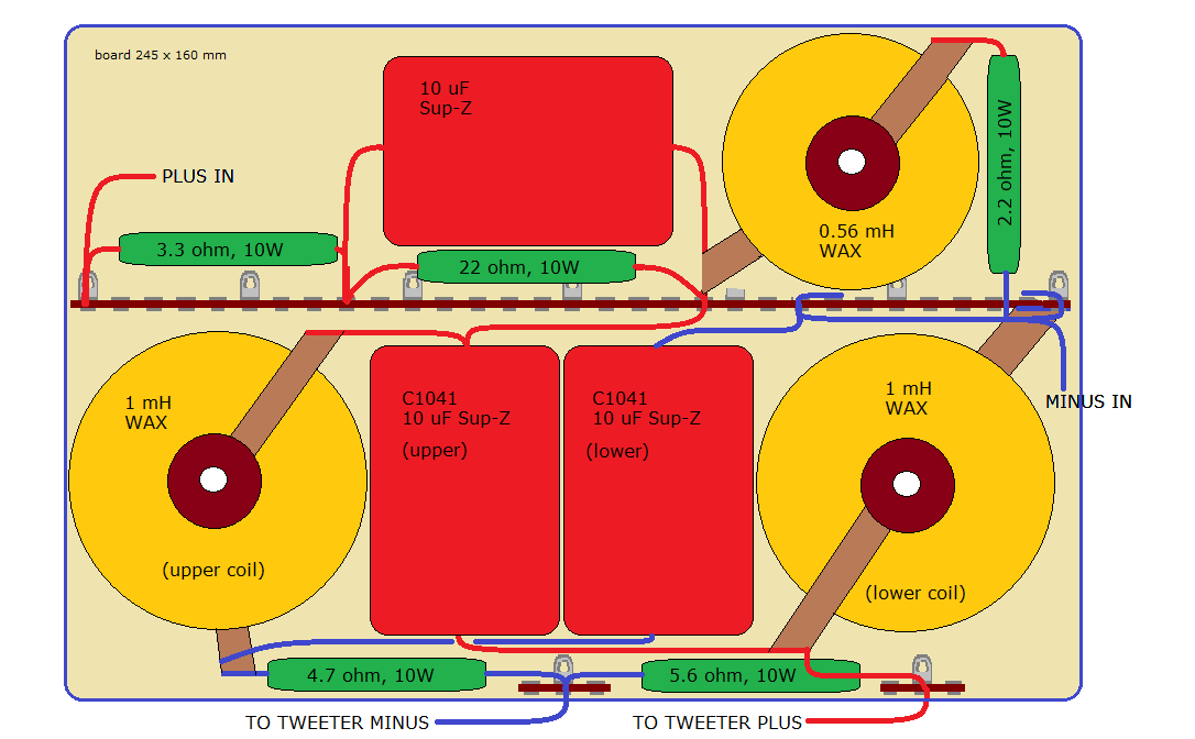
damping of peak at 4-6 kHz. The tweeter high-pass filter is a bit
unusual as it provides compensation for the delayed response from the
woofer and allows drivers to be connected with the same polarity.
Bottom line is that we can manage a close-to-perfect LR2 topology. We
could have made a stepped front panel with the tweeter retracted 35
mm, throw out the all-pass filter, connect the tweeter with inverted
polarity and we would get the same response as shown below. 35 mm
retraction is likely to cause some disturbance for the the tweeter
response with subsequent corrections. In short, it wasn't tried.
And yes, the tweeter PLUS goes to what appears to be minus but as can
be seen from step response below both drivers now have positive
response due to the all-pass section.
Numerous crossovers went
before the one shown above but they never really matched the easy flow
of upper mid/lower treble. The quick'n dirty goes like this:
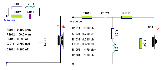
Works well on all
parameters - except sound. Not the level of transparency the drivers
are capable of and some harshness to vocals and strings. The quick'n
dirty is basically a 2nd order filter providing a 3rd order acoustic
roll-off (Butterworth). It provides slightly better power handling but
at the expense of other parameters as pointed out.
Tweeter attenuation: I
recently had a mail for a builder complaining about lack of treble
from his construction and fortunately he had measuring equipment
allowing comparison. It turned out he really like his current speakers
better due to 6-7 dB higher treble level. Now, that is a lot! If you
take a look at measurements show below and elevate treble level some
5-6 dB we're there. With the 7100 tweeter it could actually be done,
but it would sound terrible. The graphs below is from R1011 = 2.2 ohm
providing an almost flat response. Lots of detail and see-through. I
suggest trying 3.3 and 4.7 ohm for R1011 to render a more true
presentation of the treble range. Additional resistors provided with
the kit.
Measurements
BACK
TO TOP
Measurements may give us an idea
of tonal balance of a system, i.e. too much or too little energy in
certain areas. Measurements may tell us about bass extension if
far-field measurements are merged with near-field measurements. In
addition to this ports may contribute to bass extension. Most of us
diy'ers do not have access to an anechoic room for full-range
measurements from 20-20000 Hz.
What cannot be seen is what kind of bass performance we get in a
given room. Bass performance is highly dependent on in-room
placement of your speaker and the same speaker can be boomy in one
place and lean in another. Actual SPL level at 1 meter distance and
2.8V input is useful for en estimate of system sensitivity and
combined with the impedance profile may give an idea of how
powerful an amplifier is needed to drive the speaker to adequate
levels.
What measurements do not tell is the very sound of the speaker
unless displaying serious linear distortion. The level of
transparency, the ability to resolve micro-details, the
"speed" of the bass, etc., cannot be derived from these
data. Distortion measurements rarely tell anything unless seriously
bad and most modern drivers display low distortion within their
specified operating range.
Many people put way too much into these graphs and my comments here
are only meant as warning against over-interpretation. There are
way more to good sound than what can be extracted from a few
graphs. I think I speak for all of us doing speaker measurements
when I say that we learn new things every time we do one. Every
graph needs interpretation in terms of what it means sonically and
how it impacts our choice of mating drivers, cabinet and crossover
design.
Left: Response of system from 400-10000
Hz with input normalised for 2.8V/1m. System sensitivity = ~85 dB/2.8
volts. Right: 200-30000 Hz displayed.
Left: Point of crossover around 1.8 kHz,
12 dB/octave. Right: Impact of RC circuit across L2011.
Left: The tweeter roll-off could be
further smoothed by an LCR circuit across tweeter terminals, e.g. 1 mH/68uF/4R7.
Listening tests at quite loud levels didn't suggest this tweak
imperative. Right: System impedance, minimum = 6 ohms. No particular
difficult load on the amplifier.
Left: Vent tuning from port as-is (black) and with felt inserted (red). Right: Horizontal
dispersion at 0o, 10o, 20o
and 30o.
Left: CSD at 25 dB scaling. Right: Step response.
Left: 2nd and 3rd harmonic dist. shown @ 2.8V input. Right: THD shown
@ 2.8V input. Equivalent to around 85 dB/1 meter.
Left: 2nd and 3rd harmonic dist. shown @ 5.6V input (disregard red
graph). Right: THD shown @ 5.6V input. Equivalent to around 91 dB/1
meter.
CROSSOVER
KIT
BACK
TO TOP
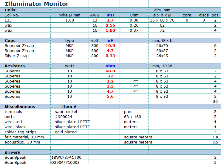
Please source components locally.
Crossover Layout
BACK
TO TOP
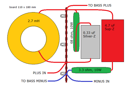
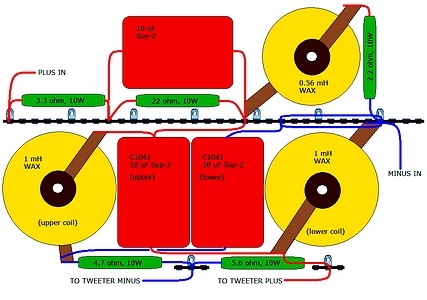
Click images to view
large. The terms "upper" coil and cap refers to the
orientation of components shown in schematics.
0.33 uF does not come as Superior-Z, thus Silver-Z.
If you use standard PP caps and wire coils all of this will take up
significant less space - but sound will deteriorate. |